Steering. Land Cruiser. Urj200, 202 Grj200 Vdj200
Variable Gear Ratio Steering. Land Cruiser. Urj200, 202 Grj200 Vdj200
Steering Actuator -- Installation |
- HINT:
- Use the same procedure for RHD and LHD vehicles.
- The procedure listed below is for LHD vehicles.
| 1. HANDLING PRECAUTIONS FOR STEERING ACTUATOR ASSEMBLY |
- NOTICE:
- Be careful that the No. 2 seal lip or boot does not turn outward while carrying or installing the steering actuator assembly. If installing a new steering actuator assembly, make sure that the spiral center lock pin is securely inserted.
- Do not use the steering actuator assembly if it has been dropped.

| 2. INSTALL STEERING ACTUATOR ASSEMBLY |
Make sure that the power steering link assembly is centered.
Install the steering actuator assembly.
If installing a new steering actuator assembly:
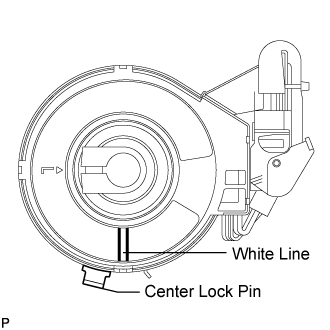
Install the steering actuator assembly with the white paint on the upper surface of the spiral case facing down.- NOTICE:
- Do not pull out the center lock pin.
If reinstalling the removed steering actuator assembly:
- Slowly turn the spiral case clockwise until it locks.
- Turn the spiral case two turns counterclockwise from the lock position.
- Align the slit of the sliding yoke with the alignment mark (▲).
- Install the steering actuator assembly with the white paint on the upper surface of the spiral case facing down.
- Slowly turn the spiral case clockwise until it locks.

 |
Align the matchmarks on the No. 2 steering intermediate shaft and steering actuator.
- NOTICE:
- Do not fold back the boot part of the steering hole cover or turn it excessively. If it is turned excessively, return it to its original position.
- Do not turn the actuator body and the spiral case.
- HINT:
- Install the steering actuator from the inside of the vehicle.
 |
Install the bolt.
- Torque:
- 35 N*m{357 kgf*cm, 26 ft.*lbf}
Using needle nose pliers, lock the clamp to the steering column hole cover to install it.
- NOTICE:
- Be careful when performing the operation as the clamp may not lock if the claws of the clamp are deformed.
 |
Move the lock in the direction of the arrow and connect the steering actuator connector.
- HINT:
- When a new actuator is installed, remove the center lock pin.
 |
Connect the connector.
| 3. INSTALL STEERING COLUMN ASSEMBLY |
| 4. CONNECT CABLE TO NEGATIVE BATTERY TERMINAL |
- NOTICE:
- Reset the AUTO TILT AWAY function setting to the previous condition by changing the customize parameter (Click here).
- When disconnecting the cable, some systems need to be initialized after the cable is reconnected (Click here).
| 5. INSPECT SRS WARNING LIGHT |
| 6. PERFORM VARIABLE GEAR RATIO STEERING SYSTEM CALIBRATION |