INSTALL STEERING WHEEL BOSS LOWER COVER (w/o Steering Heater)
INSTALL STEERING PAD SWITCH ASSEMBLY (w/ Steering Pad Switch)
INSTALL CRUISE CONTROL MAIN SWITCH (w/ Cruise Control System)
PERFORM VARIABLE GEAR RATIO STEERING SYSTEM CALIBRATION (w/ VGRS)
Steering Wheel -- Installation |
| 1. INSTALL STEERING WHEEL BOSS LOWER COVER (w/o Steering Heater) |
for Type A:
Attach the 4 claws and 2 screws and install the steering wheel boss lower cover.
for Type B:
Attach the 6 claws and install the steering wheel boss lower cover.
| 2. INSTALL STEERING SHAKE DAMPER (w/ Steering Shake Damper) |
Install the 2 screws to steering shake damper.
| 3. INSTALL NO. 1 STEERING WHEEL ORNAMENT (for Type B) |
Attach the 2 claws and 2 bolts, NO. 1 steering wheel ornament
| 4. INSTALL NO. 2 STEERING WHEEL ORNAMENT (for Type B) |
- HINT:
- Refer to "INSTALL NO. 1 STEERING WHEEL ORNAMENT".
| 5. INSTALL STEERING PAD COVER LH (w/o Steering Pad Switch) |
Install the screw and 4 guide pins, install the steering pad cover LH.
| 6. INSTALL STEERING PAD COVER RH (w/o Steering Pad Switch) |
Install the screw and 4 guide pins, install the steering pad cover RH.
| 7. INSTALL STEERING PAD SWITCH ASSEMBLY (w/ Steering Pad Switch) |
Attach the 4 claws and 4 guide pins to install the steering pad switch assembly.
Install the 4 screws.
| 8. INSTALL STEERING PAD SWITCH LH |
- HINT:
- Refer to "INSTALL STEERING PAD SWITCH ASSEMBLY".
| 9. INSTALL CRUISE CONTROL MAIN SWITCH (w/ Cruise Control System) |
Connect the connector to install the cruise control main switch wire.
Install the cruise control main switch with the 2 screws.
- Torque:
- 2.4 N*m{24 kgf*cm, 22 in.*lbf}
Connect the connector.
| 10. ADJUST SPIRAL CABLE |
Check that the ignition switch is off.
Check that the cable is disconnected from the battery negative (-) terminal.
- CAUTION:
- Wait at least 90 seconds after disconnecting the cable from the negative (-) battery terminal to disable the SRS system.
Check the check window shown in the illustration.
- HINT:
- When the spiral cable is centered, the connector is at the top and align the matchmarks to check the U-turn point of the cable from the check window.
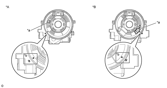
Text in Illustration *A w/o Steering Heater *B w/ Steering Heater *a Check Window *b Matchmark 
U-turn Point - -
If the spiral cable is not centered, center it.
While pushing on the interlock indicated in the illustration, rotate the spiral cable counterclockwise slowly by hand until it stops.
Text in Illustration 
Interlock - NOTICE:
- When rotating the spiral cable, make sure to push on the interlock indicated in the illustration to release the interlock mechanism.
- Do not turn the spiral cable using the airbag wire harness.
While pushing on the interlock, rotate the spiral cable 2.5 times clockwise from the lock position to align the matchmarks and check the check window.
- HINT:
- The spiral cable will rotate approximately 2.5 turns to both the left and right from the center.
- When the spiral cable is centered, the connector is at the top and align the matchmarks to check the U-turn point of the cable from the check window.
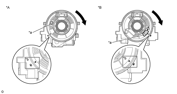
If the spiral cable cannot be centered, it is possible that the spiral cable is broken. Replace the spiral cable with a new one.Text in Illustration *A w/o Steering Heater *B w/ Steering Heater *a Check Window *b Matchmark Interlock U-turn Point
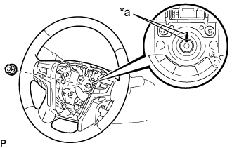
| 11. INSTALL STEERING WHEEL ASSEMBLY |
for Type A:
Align the matchmarks on the steering wheel assembly and steering main shaft assembly.
Text in Illustration *a Matchmark

for Type B:
Align the matchmarks on the steering wheel assembly and steering main shaft assembly.
Text in Illustration *a Matchmark
Install the steering wheel assembly set nut.
- Torque:
- 50 N*m{510 kgf*cm, 37 ft.*lbf}
| 12. INSTALL STEERING PAD |
| 13. CONNECT CABLE TO NEGATIVE BATTERY TERMINAL |
- NOTICE:
- When disconnecting the cable, some systems need to be initialized after the cable is reconnected (Click here).
| 14. CHECK SRS WARNING LIGHT |
| 15. PERFORM VARIABLE GEAR RATIO STEERING SYSTEM CALIBRATION (w/ VGRS) |