Light Control Rheostat -- Removal |
- HINT:
- Use the same procedure for RHD and LHD vehicles.
- The procedure listed below is for LHD vehicles.
| 1. DISABLE AUTOAWAY/RETURN FUNCTION (for Power Tilt and Power Telescopic Steering Column) |
Disable the autoaway/return function by changing the customize parameter (Click here).
- CAUTION:
- Record the current customize parameter setting (whether the autoaway/return function is enabled or disabled) in order to restore the current setting after finishing the operation.
- HINT:
- Performing the above operation causes the autoaway/return function to be disabled when the engine switch is turned off.
Turn the engine switch on (IG). Operate the tilt and telescopic switch to fully extend and lower the steering column assembly.
Turn the ignition switch off.
| 2. REMOVE NO. 2 INSTRUMENT PANEL FINISH PANEL CUSHION |
for Type A:
Put protective tape around the No. 2 instrument panel finish panel cushion.
Text in Illustration *a Protective Tape Using a moulding remover B, detach the 4 claws and 3 clips and remove the No. 2 instrument panel finish panel cushion.
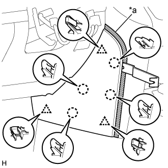
for Type B:
Put protective tape around the No. 2 instrument panel finish panel cushion.
Text in Illustration *a Protective Tape Using a moulding remover, detach the 7 claws and remove the No. 2 instrument panel finish panel cushion.
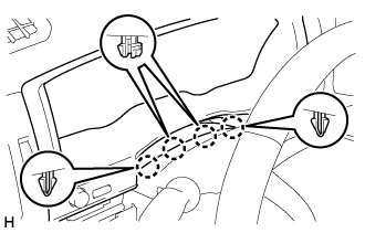
| 3. REMOVE LOWER INSTRUMENT PANEL PAD SUB-ASSEMBLY LH |
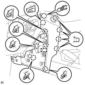
for Type A:
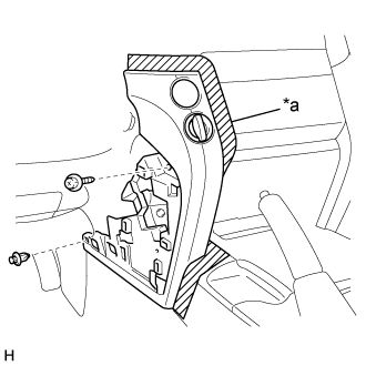
Put protective tape around the lower instrument panel pad sub-assembly LH.
Text in Illustration *a Protective Tape Remove the clip and screw.
Detach the 11 claws and guide.
Disconnect the connector and detach the clamps and remove the lower instrument panel pad sub-assembly LH.
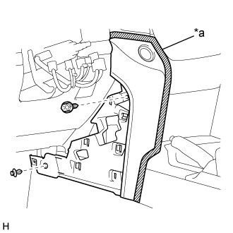
for Type B:
Put protective tape around the lower instrument panel pad sub-assembly LH.
Text in Illustration *a Protective Tape Remove the clip and screw.
Detach the 8 claws and 2 guides and remove the lower instrument panel pad sub-assembly LH.
| 4. REMOVE NO. 1 INSTRUMENT CLUSTER FINISH PANEL GARNISH |
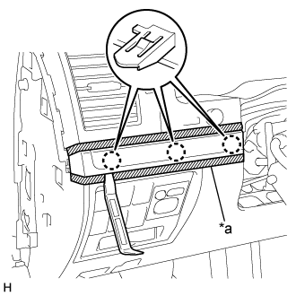 |
Put protective tape around the No. 1 instrument cluster finish panel garnish.
Text in Illustration *a Protective Tape
Using a moulding remover A, detach the 3 claws and remove the No. 1 instrument cluster finish panel garnish.
| 5. REMOVE NO. 2 INSTRUMENT CLUSTER FINISH PANEL GARNISH |
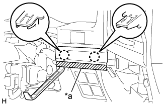 |
Put protective tape around the No. 2 instrument cluster finish panel garnish.
Text in Illustration *a Protective Tape
Using a moulding remover A, detach the 2 claws and remove the No. 2 instrument cluster finish panel garnish.
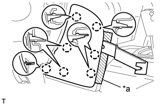
| 6. REMOVE NO. 2 INSTRUMENT CLUSTER FINISH PANEL SUB-ASSEMBLY |
 |
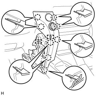
Put protective tape around the No. 2 instrument cluster finish panel sub-assembly.
Text in Illustration *a Protective Tape
Detach the 4 claws.
 |
Detach the 9 claws.
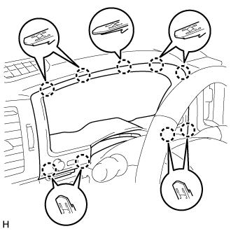 |
Disconnect the connectors and remove the No. 2 instrument cluster finish panel sub-assembly.
| 7. REMOVE LIGHT CONTROL RHEOSTAT |
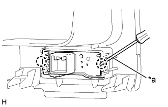 |
Using a screwdriver, detach the 2 claws and remove the light control rheostat.
- HINT:
- Tape the screwdriver tip before use.
Text in Illustration *a Protective Tape