Vehicle Exterior. Land Cruiser. Urj200, 202 Grj200 Vdj200
Exterior Panels Trim. Land Cruiser. Urj200, 202 Grj200 Vdj200
INSTALL FRONT TELEVISION CAMERA ASSEMBLY (w/ Multi-terrain Monitor)
INSTALL MILLIMETER WAVE RADAR SENSOR ASSEMBLY (w/ Dynamic Radar Cruise Control System)
Radiator Grille -- Reassembly |
| 1. INSTALL RADIATOR GRILLE EMBLEM |
Attach the 4 claws, and 2 guides to install the radiator grille emblem.
Install 2 new spring nuts.
| 2. INSTALL UPPER RADIATOR SEAL |
Attach the 14 clips to install the upper radiator seal.
| 3. INSTALL FRONT TELEVISION CAMERA ASSEMBLY (w/ Multi-terrain Monitor) |
Attach the 2 guides and 2 screws to install the front television camera assembly.
Connect the connector.
| 4. INSTALL MILLIMETER WAVE RADAR SENSOR ASSEMBLY (w/ Dynamic Radar Cruise Control System) |
- NOTICE:
- If the front bumper assembly or radiator grill has been replaced, check that the beam axis change mechanism is at the standard position (centered).
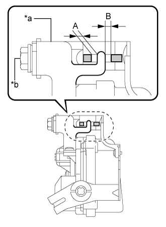
Set beam axis to the standard position.
Turn the bolt so that the beam axis change mechanism is positioned as shown in the illustration.
- Specified Condition:
- Difference between (A) and (B): 1 mm (0.0394 in.) or less
- NOTICE:
- The beam axis change mechanism may be damaged if torque exceeding the specified amount (1.5 N*m{15kgf*cm.13 in.*lbf}) is applied.
Text in Illustration *a Beam Axis Change Mechanism *b Bolt
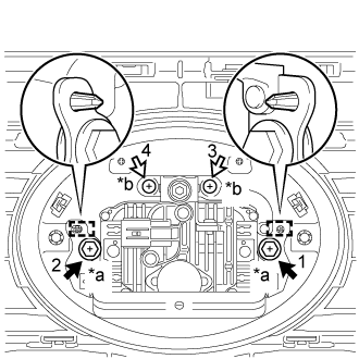
Attach the 2 guides.
Tighten the 2 bolts and 2 screws on the millimeter wave radar sensor assembly.
- Torque:
- Bolt:
- 2.5 N*m{25 kgf*cm, 22 in.*lbf}
- HINT:
- Tighten the bolts and screws in the order indicated in the illustration.
Text in Illustration *a Bolt *b Screw
 |
Connect the connector.