Audio Visual Telematics. Land Cruiser. Urj200, 202 Grj200 Vdj200
Park Assist Monitoring. Land Cruiser. Urj200, 202 Grj200 Vdj200
Toyota Parking Assist-Sensor System -- Terminals Of Ecu |
| CHECK PARK ASSIST ECU (w/ Side Monitor System) |
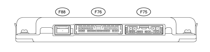
Disconnect the F75 and F76 parking assist ECU connectors.
Measure the voltage and resistance according to value(s) in the table below.
Terminal No. (Symbol) Wiring Color Terminal Description Condition Specified Condition F75-1 (+B) - F75-4 (GND1) L - W-B Power source signal Always 11 to 14 V F75-4 (GND1) - Body ground W-B - Body ground Ground Always Below 1 Ω F76-25 (CSSW) - F75-4 (GND1) Y - W-B back sonar or clearance sonar switch assembly power source signal Engine switch on (IG), back sonar or clearance sonar switch assembly on 11 to 14 V Engine switch on (IG), back sonar or clearance sonar switch assembly off Below 1 V F75-8 (IG) - F75-4 (GND1) G - W-B IG power source signal Engine switch on (IG) 11 to 14 V Engine switch off Below 1 V F75-9 (ACC) - F75-4 (GND1) GR - W-B ACC power source signal Engine switch on (ACC) 11 to 14 V Engine switch off Below 1 V Reconnect the F75 and F76 parking assist ECU connectors.
Measure the voltage and waveform according to value(s) in the table below.
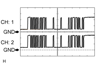
Terminal No. (Symbol) Wiring Color Terminal Description Condition Specified Condition F76-3 (LIN2) - F76-4 (CSG2) LG - GR Rear sensor circuit power source Engine switch on (IG), back sonar or clearance sonar switch assembly on Waveform 1 F76-5 (CSB1) - F76-6 (CSG1) GR - R Front sensor circuit power source Engine switch off Below 1 V Engine switch on (IG), back sonar or clearance sonar switch assembly on 7.2 to 8.8 V F75-6 (EF) - F75-7 (BBZ) L - G No. 1 clearance warning buzzer signal Buzzer does not sound Below 1 V Buzzer sounding Waveform 2 F76-20 (CSB2) - F76-4 (CSG2) R - GR Rear sensor circuit power source Engine switch on (IG), back sonar or clearance sonar switch assembly on 7.2 to 8.8 V Engine switch off Below 1 V F76-23 (LIN1) - F76-6 (CSG1) LG - R Front sensor circuit power source Engine switch on (IG), back sonar or clearance sonar switch assembly on Waveform 1 Using an oscilloscope, check waveform 1.
Waveform 1 (Reference) Item Content Terminal No. (Symbol) - F76-3 (LIN2) - F76-4 (CSG2)
- F76-23 (LIN1) - F76-6 (CSG1)
Tool Setting 2 V/DIV., 1 msec./DIV. Condition Engine switch on (IG), back sonar or clearance sonar switch assembly on - F76-3 (LIN2) - F76-4 (CSG2)
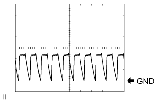
Using an oscilloscope, check waveform 2.
Waveform 2 (Reference) Item Content Terminal No. (Symbol) F75-6 (EF) - F75-7 (BBZ) Tool Setting 5 V/DIV., 1 msec./DIV. Condition Engine switch on (IG), shift lever moved to R - NOTICE:
- The waveform amplitude varies depending on the volume setting.
 |
 |
| CHECK CLEARANCE WARNING ECU ASSEMBLY (w/o Side Monitor System) |

Disconnect the F12 clearance warning ECU assembly connector.
Measure the voltage and resistance according to value(s) in the table below.
Terminal No. (Symbol) Wiring Color Terminal Description Condition Specified Condition F12-12 (CSSW) - F12-17 (GND1) Y - W-B back sonar or clearance sonar switch assembly power source signal Engine switch on (IG), back sonar or clearance sonar switch assembly on 11 to 14 V Engine switch on (IG), back sonar or clearance sonar switch assembly off Below 1 V F12-15 (IG) - F12-17 (GND1) G - W-B IG power source signal Engine switch on (IG) 11 to 14 V Engine switch off Below 1 V F12-17 (GND1) - Body ground W-B - Body ground Ground Always Below 1 Ω Reconnect the F12 clearance warning ECU assembly connector.
Measure the voltage and waveform according to value(s) in the table below.
Terminal No. (Symbol) Wiring Color Terminal Description Condition Specified Condition F12-7 (CSB2) - F12-18 (CSG2) R - GR Rear sensor circuit power source Engine switch on (IG), back sonar or clearance sonar switch assembly on 7.2 to 8.8 V Engine switch off Below 1 V F12-9 (LIN1) - F12-19 (CSG1) LG - R Front sensor circuit power source Engine switch on (IG), back sonar or clearance sonar switch assembly on Waveform 1 F12-10 (BBZ) - F12-11 (EF) G - L No. 1 clearance warning buzzer signal Buzzer not sounding Below 1 V Buzzer sounding Waveform 2 F12-21 (CSB1) - F12-9 (LIN1) GR - LG Front sensor circuit power source Engine switch on (IG), back sonar or clearance sonar switch assembly on 7.2 to 8.8 V Engine switch off Below 1 V F12-24 (LIN2) - F12-18 (CSG2) LG - GR Rear sensor circuit power source Engine switch on (IG), back sonar or clearance sonar switch assembly on Waveform 1 Using an oscilloscope, check waveform 1.
Waveform 1 (Reference) Item Content Terminal No. (Symbol) - F12-9 (LIN1) - F12-19 (CSG1)
- F12-24 (LIN2) - F12-18 (CSG2)
Tool Setting 2 V/DIV., 1 msec./DIV. Condition Engine switch on (IG), back sonar or clearance sonar switch assembly on - F12-9 (LIN1) - F12-19 (CSG1)
Using an oscilloscope, check waveform 2.
Waveform 2 (Reference) Item Content Terminal No. (Symbol) F12-10 (BBZ) - F12-11 (EF) Tool Setting 5 V/DIV., 1 msec./DIV. Condition Engine switch on (IG), shift lever moved to R - NOTICE:
- The waveform amplitude varies depending on the volume setting.
|
|