Engine Unit -- Removal |
| 1. REMOVE ENGINE WIRE |
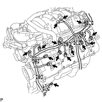 |
Engine LH Side:
Disconnect the 2 camshaft timing control valve connectors.
Disconnect the 4 ignition coil connectors.
Disconnect the 2 VVT sensor connectors.
Disconnect the camshaft position sensor connector.
Disconnect the vacuum switching valve connector (for ACIS).
Disconnect the purge VSV connector.
Disconnect the engine coolant temperature sensor connector.
Disconnect the fuel injector connector.
Disconnect the noise filter connector.
Remove the bolt and disconnect the 7 clamps.
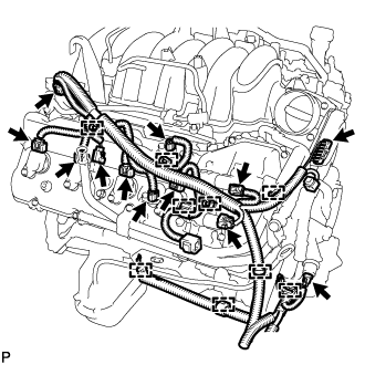
Engine RH Side:
Disconnect the 2 camshaft timing control valve connectors.
Disconnect the 4 ignition coil connectors.
Disconnect the 2 VVT sensor connectors.
Disconnect the fuel injector connector.
Disconnect the noise filter connector.
Disconnect the throttle sensor connector.
Disconnect the oil pressure sender gauge connector.
Disconnect the 9 clamps.
 |
Engine Rear Side:
Disconnect the sensor wire connector.
Disconnect the 5 clamps.
Remove the 3 bolts.
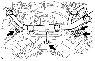 |
Remove the engine wire.
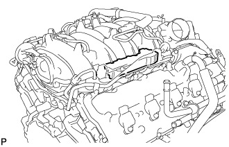
| 2. REMOVE NO. 1 ENGINE COVER SUB-ASSEMBLY |
Remove the No. 1 engine cover sub-assembly.
 |
| 3. REMOVE NO. 3 ENGINE COVER |
Remove the No. 3 engine cover.
 |
| 4. REMOVE NO. 1 FUEL HOSE |
 |
Remove the fuel hose (Click here).
| 5. DISCONNECT NO. 2 FUEL TUBE |
Disconnect the No. 2 fuel tube from the fuel pressure regulator (Click here).
 |
| 6. DISCONNECT NO. 1 FUEL TUBE |
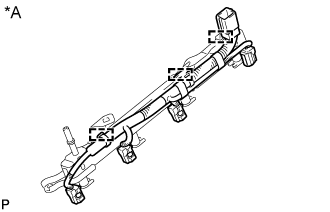
Disconnect the No. 1 fuel tube from the fuel delivery pipe RH (for metallic type) (Click here).
- SST
- 09268-21011
Text in Illustration *A RH Side
 |
LH Side:
Disconnect the No. 1 fuel tube from the fuel delivery pipe LH (Click here).Text in Illustration *A LH Side
 |
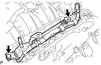
| 7. REMOVE FUEL DELIVERY PIPE SUB-ASSEMBLY LH |
Disconnect the No. 7 wire harness connector.
Remove the 2 bolts and fuel delivery pipe LH.
- NOTICE:
- When removing the delivery pipe, hold the pipe by both ends and pull it straight upward.
 |
Remove the 2 delivery pipe spacers and 4 insulators from the cylinder head LH.
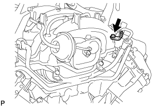
| 8. REMOVE FUEL DELIVERY PIPE SUB-ASSEMBLY RH |
Disconnect the ventilation hose and No. 6 wire harness connector.
 |
Remove the 2 bolts and fuel delivery pipe RH.
- NOTICE:
- When removing the delivery pipe, hold the pipe by both ends and pull it straight upward.
 |
Remove the 2 delivery pipe spacers and 4 insulators from the cylinder head RH.
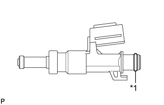
| 9. REMOVE FUEL INJECTOR ASSEMBLY |
Remove the fuel injector from the fuel delivery pipe, and then disconnect the injector connector.
- NOTICE:

- For reinstallation, attach a tag or label to the injector shaft.
 |
Remove the O-ring from the fuel injector.
Text in Illustration *1 O-Ring
 |
Detach the 3 clamps and then remove the No. 6 wire harness from the delivery pipe RH.
Text in Illustration *A Fuel Delivery Pipe RH
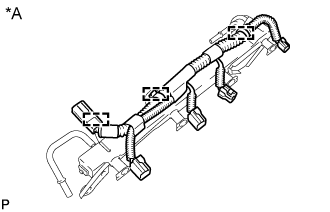 |
Detach the 3 clamps and then remove the No. 7 wire harness from the delivery pipe LH.
Text in Illustration *A Fuel Delivery Pipe LH
 |
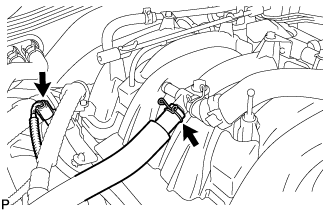
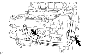
| 10. REMOVE INTAKE MANIFOLD |
Disconnect the ventilation hose from the ventilation pipe of the cylinder head cover LH and RH.
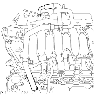 |
Disconnect the 2 water by-pass hoses.
 |
Disconnect the No. 1 ventilation hose.
 |
Remove the bolt and wire bracket from the intake manifold.
 |
Remove the 2 nuts, 8 bolts, intake manifold and 2 gaskets.
 |
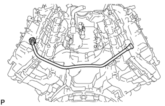
| 11. REMOVE NO. 2 FUEL TUBE |
 |
Remove the 2 bolts and No. 2 fuel tube.
| 12. REMOVE NO. 1 FUEL TUBE |
 |
| 13. REMOVE NO. 2 ENGINE COVER |
 |
| 14. REMOVE NO. 1 ENGINE COVER |
 |
| 15. REMOVE NO. 2 WATER BY-PASS PIPE SUB-ASSEMBLY |
Remove the 3 bolts.
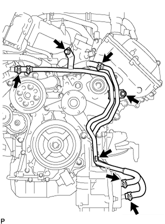 |
Disconnect the 4 hoses and remove the water by-pass pipe.
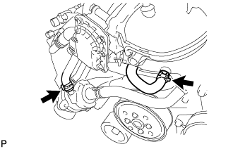
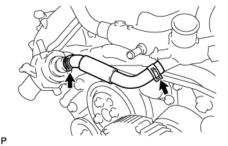
| 16. REMOVE NO. 1 WATER BY-PASS HOSE |
Remove the No. 1 water by-pass hose by disconnecting the hose from the water inlet housing and front water by-pass joint.
 |
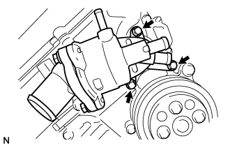
| 17. REMOVE FRONT WATER BY-PASS JOINT |
Disconnect the No. 2 water by-pass hose from the water by-pass joint.
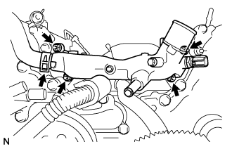 |
Remove the 4 nuts, water by-pass joint and 2 gaskets.
| 18. REMOVE WATER INLET HOUSING |
Remove the 3 bolts, water inlet housing and gasket.
 |
| 19. REMOVE WATER BY-PASS PIPE SUB-ASSEMBLY |
 |
Remove the 2 bolts and water by-pass pipe.
| 20. REMOVE SENSOR WIRE |
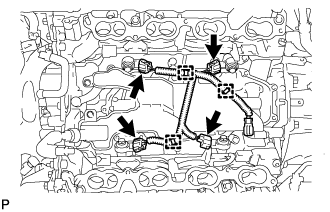 |
Disconnect the 4 knock sensor connectors.
Disconnect the 3 clamps. Then remove the sensor wire.
| 21. REMOVE SEPARATOR CASE |
Remove the 4 bolts and separator case.
 |
| 22. REMOVE KNOCK SENSOR |
Remove the 4 bolts and 4 knock sensors.
 |
| 23. REMOVE CYLINDER BLOCK WATER DRAIN COCK SUB-ASSEMBLY |
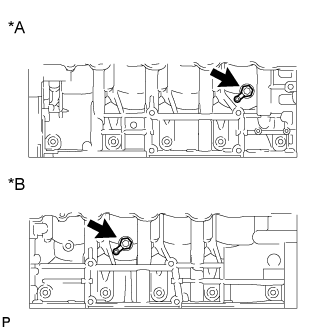 |
Remove the 2 water drain cock plugs from the water drain cocks.
Remove the 2 water drain cocks from the cylinder block.
Text in Illustration *A RH *B LH
| 24. REMOVE FRONT NO. 1 ENGINE MOUNTING BRACKET RH |
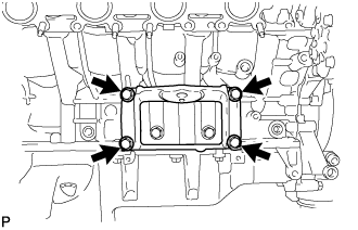 |
Remove the 4 bolts and mounting bracket.
| 25. REMOVE FRONT NO. 1 ENGINE MOUNTING BRACKET LH |
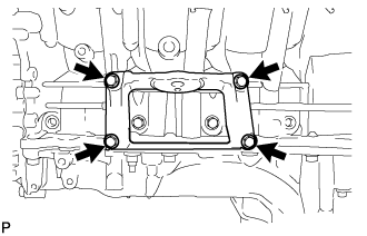 |
Remove the 4 bolts and mounting bracket.
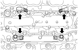
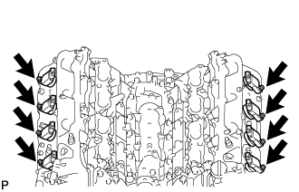
| 26. REMOVE IGNITION COIL ASSEMBLY |
Remove the 8 bolts and 8 ignition coils.
 |
| 27. REMOVE NOISE FILTER |
Remove the 2 bolts and 2 noise filters from the cylinder head cover.