Vehicle Exterior. Land Cruiser. Urj200, 202 Grj200 Vdj200
Window Glass. Land Cruiser. Urj200, 202 Grj200 Vdj200
Windshield Deicer System -- Terminals Of Ecu |
| CHECK AIR CONDITIONING AMPLIFIER ASSEMBLY (w/ Rear Heater) |
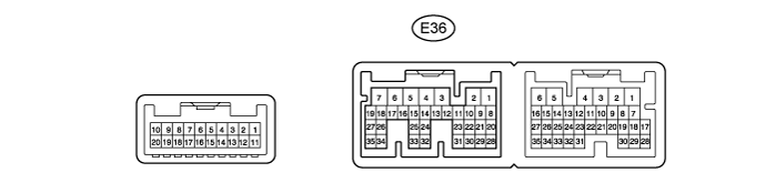
Disconnect the E36 air conditioning amplifier assembly connector.
Measure the resistance and voltage according to the value(s) in the table below.
Terminal No. (Symbol) Wiring Color Terminal Description Condition Specified Condition E36-5 (IG+) - E36-1 (GND) G - W-B Power source (IG) Ignition switch ON 11 to 14 V Ignition switch off Below 1 V E36-6 (+B1) - E36-1 (GND) R - W-B Power source Always 11 to 14 V E36-7 (+B2) - E36-1 (GND) R - W-B Power source Always 11 to 14 V E36-1 (GND) - Body ground W-B - Body ground Ground Always Below 1 Ω - If the result is not as specified, there may be a malfunction on the wire harness side.
- If the result is not as specified, there may be a malfunction on the wire harness side.
Reconnect the E36 air conditioning amplifier assembly connector.
Measure the voltage according to the value(s) in the table below.
Terminal No. (Symbol) Wiring Color Terminal Description Condition Specified Condition E36-23 (FDEF) - E36-1 (GND) GR - W-B Deicer relay Ignition switch ON and deicer switch off 11 to 14 V Ignition switch ON and deicer switch on Below 1 V
| CHECK AIR CONDITIONING AMPLIFIER ASSEMBLY (w/o Rear Heater) |
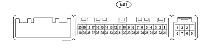
Disconnect the E81 air conditioning amplifier assembly connector.
Measure the resistance and voltage according to the value(s) in the table below.
Terminal No. (Symbol) Wiring Color Terminal Description Condition Specified Condition E81-1 (IG+) - E81-14 (GND) G - W-B Power source (IG) Ignition switch ON 11 to 14 V Ignition switch off Below 1 V E81-21 (+B1) - E81-14 (GND) R - W-B Power source Always 11 to 14 V E81-14 (GND) - Body ground W-B - Body ground Ground Always Below 1 Ω - If the result is not as specified, there may be a malfunction on the wire harness side.
- If the result is not as specified, there may be a malfunction on the wire harness side.
Reconnect the E81 air conditioning amplifier assembly connector.
Measure the voltage according to the value(s) in the table below.
Terminal No. (Symbol) Wiring Color Terminal Description Condition Specified Condition E81-40 (FDEF) - E81-14 (GND) GR - W-B Deicer relay Ignition switch ON and deicer switch off 11 to 14 V Ignition switch ON and deicer switch on Below 1 V
| CHECK AIR CONDITIONING CONTROL ASSEMBLY (w/o Navigation System) |

Disconnect the F10 air conditioning control assembly connector.
Measure the resistance and voltage according to the value(s) in the table below.
Terminal No. (Symbol) Wiring Color Terminal Description Condition Specified Condition F10-7 (IG+) - F10-1 (GND) G - W-B Power source (IG) Ignition switch ON 11 to 14 V Ignition switch off Below 1 V F10-1 (GND) - Body ground W-B - Body ground Ground Always Below 1 Ω - If the result is not as specified, there may be a malfunction on the wire harness side.
- If the result is not as specified, there may be a malfunction on the wire harness side.
| MULTI-MEDIA MODULE RECEIVER ASSEMBLY (w/ Navigation System) |
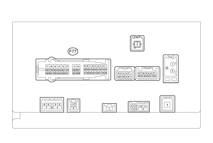
| Terminal No. (Symbol) | Wiring Color | Terminal Description | Condition | Specified Condition |
| F77-17 (+B1) - F77-12 (GND1) | R - W-B | Power source | Always | 11 to 14 V |
| F77-12 (GND1) - Body ground | W-B - Body ground | Ground | Always | Below 1 Ω |
| F77-15 (IG) - F77-12 (GND1) | G - W-B | Power source (IG) | Ignition switch ON | 11 to 14 V |
| Ignition switch off | Below 1 V | |||
| F77-16 (ACC1) - F77-12 (GND1) | GR - W-B | Power source (ACC) | Ignition switch ACC | 11 to 14 V |
| Ignition switch off | Below 1 V | |||
| F77-35 (UIND) | R | UART communication signal | - | - |
| F77-36 (UPSW) | P | UART communication signal | - | - |
| F77-1 (CANH) | P | CAN communication signal | - | - |
| F77-2 (CANL) | B | CAN communication signal | - | - |
| MULTI-DISPLAY ASSEMBLY (w/ Navigation System) |

| Terminal No. (Symbol) | Wiring Color | Terminal Description | Condition | Specified Condition |
| F79-12 (+B2) - F79-13 (GND1) | R - BR | Power source | Always | 11 to 14 V |
| F79-13 (GND1) - Body ground | BR - Body ground | Ground | Always | Below 1 Ω |
| F79-23 (IG) - F79-13 (GND1) | G - BR | Power source (IG) | Ignition switch ON | 11 to 14 V |
| Ignition switch off | Below 1 V | |||
| F79-24 (ACC) - F79-13 (GND1) | GR - BR | Power source (ACC) | Ignition switch ACC | 11 to 14 V |
| Ignition switch off | Below 1 V | |||
| F79-3 (UPSW) | P | UART communication signal | - | - |
| F79-4 (UIND) | R | UART communication signal | - | - |