INSTALL NO. 2 EMISSION CONTROL VALVE SET (w/ Secondary Air Injection System)
INSTALL NO. 1 EMISSION CONTROL VALVE SET (w/ Secondary Air Injection System)
Engine Unit -- Installation |
| 1. INSTALL FLYWHEEL RING GEAR (for Manual Transmission) |
Using a torch, heat the ring gear evenly to approximately 200°C (392°F).
Text in Illustration *1 Chamfer *2 Ring Gear *3 Flywheel - NOTICE:
- Be careful not to overheat the ring gear.
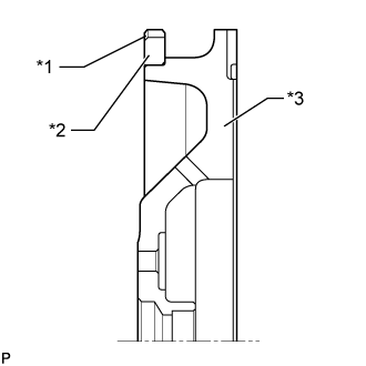 |
Using a brass bar, tap the ring gear onto the flywheel with its chamfered gear teeth facing the block.
- NOTICE:
- After installing, allow the ring gear to cool before handling.
| 2. INSTALL FRONT NO. 1 ENGINE MOUNTING BRACKET RH |
Install the front No. 1 engine mounting bracket RH with the 4 bolts.
- Torque:
- 43 N*m{438 kgf*cm, 32 ft.*lbf}
| 3. INSTALL FRONT NO. 1 ENGINE MOUNTING BRACKET LH |
Install the front No. 1 engine mounting bracket LH with the 3 bolts.
- Torque:
- 43 N*m{438 kgf*cm, 32 ft.*lbf}
| 4. INSTALL ENGINE OIL LEVEL DIPSTICK GUIDE |
Install a new O-ring to the engine oil level dipstick guide.
Text in Illustration *1 New O-Ring
 |
Apply a light coat of engine oil to the O-ring.
Push the engine oil level dipstick guide end into the guide hole.
Install the engine oil level dipstick guide with the bolt.
- Torque:
- 10 N*m{102 kgf*cm, 7 ft.*lbf}
Install the engine oil level dipstick.
| 5. INSTALL V-RIBBED BELT TENSIONER ASSEMBLY |
Temporarily install the V-ribbed belt tensioner with the 5 bolts.
- Standard Bolt:
Item Length A 70 mm (2.76 in.) B 33 mm (1.30 in.)
Text in Illustration 
Bolt A 
Bolt B
 |
Tighten bolts 1 and 2 in numerical order.
- Torque:
- 36 N*m{367 kgf*cm, 27 ft.*lbf}
Tighten the other bolts.
- Torque:
- 36 N*m{367 kgf*cm, 27 ft.*lbf}
| 6. INSTALL NO. 2 IDLER PULLEY SUB-ASSEMBLY |
Install the 2 No. 2 idler pulleys with the 2 bolts.
- Torque:
- 54 N*m{551 kgf*cm, 40 ft.*lbf}
| 7. INSTALL NO. 1 IDLER PULLEY SUB-ASSEMBLY |
Install the No. 1 idler pulley with the bolt.
- Torque:
- 54 N*m{551 kgf*cm, 40 ft.*lbf}
Text in Illustration *1 DOUBLE - HINT:
- "DOUBLE" is marked on the No. 1 idler pulley to distinguish it from the No. 2 idler pulley.
 |
| 8. INSTALL WATER BY-PASS PIPE SUB-ASSEMBLY |
Install the water by-pass pipe with the 3 bolts.
- Torque:
- 10 N*m{102 kgf*cm, 7 ft.*lbf}
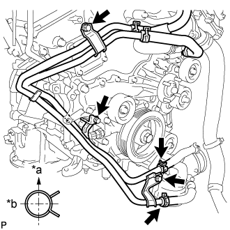 |
Connect the 2 hoses.
Text in Illustration *a Upward *b Rearward - HINT:
- The direction of the hose clamp is indicated in the illustration.
| 9. INSTALL INTAKE MANIFOLD |
Set a new gasket on each cylinder head.
- NOTICE:
- Align the port holes of the gasket and cylinder head.
- Be careful of the installation direction.
 |
Set the intake manifold on the cylinder heads.
Install and uniformly tighten the 6 bolts and 4 nuts in several passes.
- Torque:
- 21 N*m{214 kgf*cm, 15 ft.*lbf}
- HINT:
- Tighten the inner installation bolts of the intake manifold before tightening the outer bolts.
| 10. INSTALL FUEL INJECTOR ASSEMBLY |
Install a new insulator to each fuel injector.
Text in Illustration *1 New Insulator *2 New O-Ring
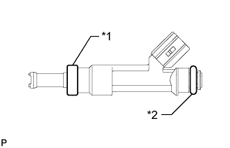 |
Apply a light coat of spindle oil or gasoline to new O-rings and install one to each fuel injector.
Install the 6 injectors.
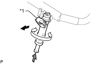
While turning each fuel injector left and right, install it to the fuel delivery pipe.
Text in Illustration *1 Connector Outward Turn 
Push Position the fuel injectors with the connectors facing outward.
| 11. INSTALL FUEL DELIVERY PIPE SUB-ASSEMBLY |
Place the fuel delivery pipe together with the 6 fuel injectors on the intake manifold.
Temporarily install the 4 bolts, which are used to hold the fuel delivery pipe in place, to the intake manifold.
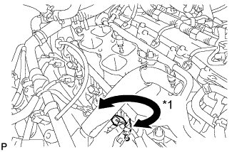
Check that the fuel injectors rotate smoothly.
If the fuel injectors do not rotate smoothly, replace the O-ring of any injector that does not rotate smoothly.Text in Illustration *1 Turn
 |
Position the fuel injectors with the connectors facing outward.
Tighten the 4 bolts.
- Torque:
- 21 N*m{214 kgf*cm, 15 ft.*lbf}
Connect the 6 fuel injector connectors.
| 12. INSTALL FUEL PIPE SUB-ASSEMBLY |
Install the No. 1 fuel pipe and No. 2 fuel pipe with the 2 bolts.
- Torque:
- 9.0 N*m{92 kgf*cm, 80 in.*lbf}
Connect the 2 fuel pipes (Click here).
| 13. INSTALL IGNITION COIL ASSEMBLY |
Install the 6 ignition coils with the 6 bolts.
- Torque:
- 10 N*m{102 kgf*cm, 7 ft.*lbf}
Connect the 6 ignition coil connectors.
| 14. INSTALL NO. 2 EMISSION CONTROL VALVE SET (w/ Secondary Air Injection System) |
Install the No. 2 emission control valve set with the 3 nuts.
- Torque:
- 21 N*m{214 kgf*cm, 15 ft.*lbf}
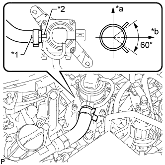
Align the paint mark with the rib and connect the No. 1 air hose.
Text in Illustration *1 Paint Mark *2 Rib *a Top *b LH Side - HINT:
- Make sure the direction of the hose clamp is as shown in the illustration.
 |
Connect the No. 2 emission control valve set connector.
| 15. INSTALL NO. 1 EMISSION CONTROL VALVE SET (w/ Secondary Air Injection System) |
Install the No. 1 emission control valve set with the 3 nuts.
- Torque:
- 21 N*m{214 kgf*cm, 15 ft.*lbf}
Align the paint mark with the rib and connect the No. 1 air hose.
Text in Illustration *1 Rib *2 Paint Mark *a RH Side *b Top - HINT:
- Make sure the direction of the hose clamp is as shown in the illustration.
 |
Connect the No. 1 emission control valve set connector.
| 16. INSTALL HEATER WATER HOSE ASSEMBLY |
Install the heater water hose assembly and connect the 2 hoses with the 2 bolts.
- Torque:
- 9.8 N*m{100 kgf*cm, 87 in.*lbf}
| 17. INSTALL ENGINE WIRE |