Power Mirror Control System (W/ Retract Mirror) -- Terminals Of Ecu |
| CHECK OUTER MIRROR CONTROL ECU ASSEMBLY LH |
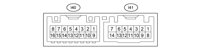
Disconnect the I41 outer mirror control ECU assembly LH connector.
Measure the voltage and resistance according to the value(s) in the table below.
Terminal No.
(Symbol)Wiring Color Terminal Description Condition Specified Condition I41-5 (SIG) - I41-7 (GND) B - W-B ACC power supply Engine switch off Below 1 V Engine switch on (ACC) 11 to 14 V I41-6 (CPUB) - I41-7 (GND) G - W-B Battery (ECU power source) Always 11 to 14 V I41-7 (GND) - Body ground W-B - Body ground Ground Always Below 1 Ω I41-14 (BDR) - I41-7 (GND) L - W-B Battery (ECU power source) Always 11 to 14 V Reconnect the I41 outer mirror control ECU assembly LH connector.
Measure the voltage and resistance according to the value(s) in the table below.
Terminal No.
(Symbol)Wiring Color Terminal Description Condition Specified Condition I40-3 (MR+) - Body ground R - Body ground Mirror retract motor output (retracting) - Engine switch on (ACC)
- Outer rear view mirror assembly LH being retracted
11 to 14 V - Engine switch on (ACC)
- Outer rear view mirror assembly LH stopped
Below 1 V I40-11 (MR-) - Body ground BR - Body ground Mirror retract motor output (returning) - Engine switch on (ACC)
- Outer rear view mirror assembly LH retuning
11 to 14 V - Engine switch on (ACC)
- Outer rear view mirror assembly LH stopped
Below 1 V I40-1 (LMVR) - Body ground R - Body ground Mirror motor output - Engine switch on (ACC)
- Mirror surface stopped
Below 1 V - Engine switch on (ACC)
- Mirror surface moving downward or left
Below 1 V - Engine switch on (ACC)
- Mirror surface moving upward
11 to 14 V I40-9 (LMHR) - Body ground G - Body ground Mirror motor output - Engine switch on (ACC)
- Mirror surface stopped
Below 1 Ω - Engine switch on (ACC)
- Mirror surface moving upward or right
Below 1 Ω - Engine switch on (ACC)
- Mirror surface moving left
11 to 14 V I40-10 (LM+R) - Body ground P - Body ground Mirror motor output - Engine switch on (ACC)
- Outer mirror LH stopped
Below 1 V - Engine switch on (ACC)
- Mirror surface moving upward or left
Below 1 V - Engine switch on (ACC)
- Mirror surface moving downward or right
11 to 14 V I40-5 (LVC) - I40-14 (LE1)*1 W - LG Mirror position sensor power supply Engine switch off Below 1 V Engine switch on (IG) 4.5 to 5.5V I40-6 (VSSR) - Body ground*1 L - Body ground Vertical direction position sensor signal - Engine switch on (ACC)
- Mirror surface moving upward or downward
Voltage fluctuates between 0 to 5 V I40-13 (HSSR) - Body ground*1 B - Body ground Horizontal direction position sensor signal - Engine switch on (ACC)
- Mirror surface moving left or right
Voltage fluctuates between 0 to 5 V I40-4 (HTR+) - I40-12 (HTR-)*2 LG - L Mirror heater drive voltage - Engine switch on (IG)
- Rear window defogger switch (mirror heater switch) off
Below 1 V - Engine switch on (IG)
- Rear window defogger switch (mirror heater switch) on
11 to 14 V I41-2 (M1) - I41-7 (GND)*1, *3 G - W-B Seat memory switch M1 signal - Engine switch on (IG)
- Seat memory switch M1 on
11 to 14 V - Engine switch on (IG)
- Seat memory switch M1 off
Below 1 V I41-3 (M2) - I41-7 (GND)*1, *3 W - W-B Seat memory switch M2 signal - Engine switch on (IG)
- Seat memory switch M2 on
11 to 14 V - Engine switch on (IG)
- Seat memory switch M2 off
Below 1 V I41-4 (M3) - I41-7 (GND)*1, *3 R - W-B Seat memory switch M3 signal - Engine switch on (IG)
- Seat memory switch M3 on
11 to 14 V - Engine switch on (IG)
- Seat memory switch M3 off
Below 1 V I41-1 (MM) - I41-7 (GND)*1, *3 B - W-B Seat memory switch SET signal - Engine switch on (IG)
- Seat memory switch SET on
11 to 14 V - Engine switch on (IG)
- Seat memory switch SET off
Below 1 V - *1: w/ Memory
- *2: w/ Mirror Heater
- *3: for LHD
- Engine switch on (ACC)
| CHECK OUTER MIRROR CONTROL ECU ASSEMBLY RH |
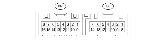
Disconnect the I38 outer mirror control ECU assembly RH connector.
Measure the voltage and resistance according to the value(s) in the table below.
Terminal No.
(Symbol)Wiring Color Terminal Description Condition Specified Condition I38-5 (SIG) - I38-7 (GND) B - W-B ACC power supply Engine switch off (IG) Below 1 V Engine switch on (IG) 11 to 14 V I38-6 (CPUB) - I38-7 (GND) G - W-B Battery (ECU power source) Always 11 to 14 V I38-7 (GND) - Body ground W-B - Body ground Ground Always Below 1 Ω I38-14 (BDR) - I38-7 (GND) L - W-B Battery (ECU power source) Always 11 to 14 V Reconnect the I38 outer mirror control ECU RH connector.
Measure the voltage and resistance according to the value(s) in the table below.
Terminal No.
(Symbol)Wiring Color Terminal Description Condition Specified Condition I37-3 (MR+) - Body ground G- Body ground Mirror retract motor output (retracting) - Engine switch on (ACC)
- Outer rear view mirror assembly RH being retracted
11 to 14 V - Engine switch on (ACC)
- Outer rear view mirror assembly RH stopped
Below 1 V I37-11 (MR-) - Body ground LG - Body ground Mirror retract motor output (returning) - Engine switch on (ACC)
- Outer rear view mirror assembly LH retuning
11 to 14 V - Engine switch on (ACC)
- Outer rear view mirror assembly LH stopped
Below 1 V I37-1 (RMVR) - Body ground R - Body ground Mirror motor output - Engine switch on (ACC)
- Mirror surface stopped
Below 1 V - Engine switch on (ACC)
- Mirror surface moving downward or left
Below 1 V - Engine switch on (ACC)
- Mirror surface moving upward
11 to 14 V I37-9 (RMHR) - Body ground G - Body ground Mirror motor output - Engine switch on (ACC)
- Mirror surface stopped
Below 1 V - Engine switch on (ACC)
- Mirror surface moving upward or right
Below 1 V - Engine switch on (ACC)
- Mirror surface moving left
11 to 14 V I37-10 (RM+R) - Body ground P - Body ground Mirror motor output - Engine switch on (ACC)
- Mirror surface stopped
Below 1 V - Engine switch on (ACC)
- Mirror surface moving upward or left
Below 1 V - Engine switch on (ACC)
- Mirror surface moving downward or right
11 to 14 V I37-5 (RVC) - I37-14 (RE1)*1 B - R Mirror position sensor power supply Engine switch off Below 1 V Engine switch on (IG) 4.5 to 5.5V I37-6 (VSSR) - Body ground*1 SB - Body ground Vertical direction position sensor signal - Engine switch on (ACC)
- Mirror surface moving upward or downward
Voltage fluctuates between 0 to 5 V I37-13 (HSSR) - Body ground*1 L - Body ground Horizontal direction position sensor signal - Engine switch on (ACC)
- Mirror surface moving left or right
Voltage fluctuates between 0 to 5 V I37-4 (HTR+) - I37-12 (HTR-)*2 SB - L Mirror heater drive voltage - Engine switch on (IG)
- Rear window defogger switch (mirror heater switch) off
Below 1 V - Engine switch on (IG)
- Rear window defogger switch (mirror heater switch) on
11 to 14 V I38-2 (M1) - I38-7(GND)*1, *3 G - W-B Seat memory switch M1 signal - Engine switch on (IG)
- Seat memory switch M1 on
11 to 14 V - Engine switch on (IG)
- Seat memory switch M1 off
Below 1 V I38-3 (M2) - I38-7(GND)*1, *3 W - W-B Seat memory switch M2 signal - Engine switch on (IG)
- Seat memory switch M2 on
11 to 14 V - Engine switch on (IG)
- Seat memory switch M2 off
Below 1 V I38-4 (M3) - I38-7(GND)*1, *3 R - W-B Seat memory switch M3 signal - Engine switch on (IG)
- Seat memory switch M3 on
11 to 14 V - Engine switch on (IG)
- Seat memory switch M3 off
Below 1 V I38-1 (MM) - I38-7(GND)*1, *3 B - W-B Seat memory switch SET signal - Engine switch on (IG)
- Seat memory switch SET on
11 to 14 V - Engine switch on (IG)
- Seat memory switch SET off
Below 1 V - *1: w/ Memory
- *2: w/ Mirror Heater
- *3: for LHD
- Engine switch on (ACC)
| CHECK MAIN BODY ECU (MULTIPLEX NETWORK BODY ECU), COWL SIDE JUNCTION BLOCK LH |
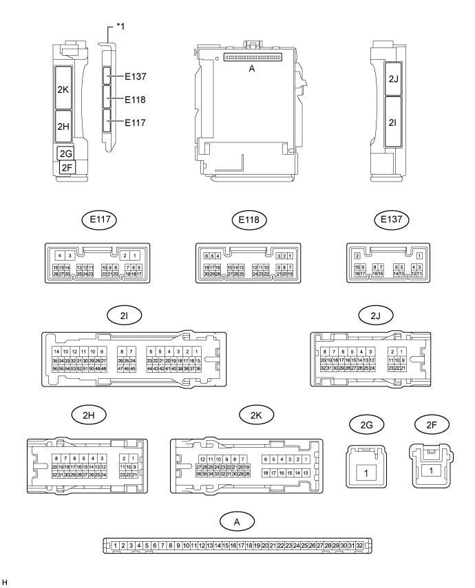
Remove the main body ECU (multiplex network body ECU) from the cowl side junction block LH .
- for LHD: Click here
- for RHD: Click here
- for LHD: Click here
Measure the voltage and resistance according to the value(s) in the table below.
Terminal No.
(Symbol)Wiring Color Terminal Description Condition Specified Condition A-32 (IG) - Body ground - IG power supply Engine switch off Below 1 V Engine switch on (IG) 11 to 14 V A-30 (ACC) - Body ground - ACC power supply Engine switch off Below 1 V Engine switch on (ACC) 11 to 14 V A-31 (BECU) - Body ground - BECU power supply Always 11 to 14 V A-11 (GND1) - Body ground - Body ground Always Below 1 Ω Install the main body ECU (multiplex network body ECU) to the cowl side junction block LH.
- for LHD: Click here
- for RHD: Click here
- for LHD: Click here
Measure the voltage and resistance according to the value(s) in the table below.
Terminal No.
(Symbol)Wiring Color Terminal Description Condition Specified Condition E117-14 (RET) - 2J-1 (GND) BE - W-B Mirror retract motor output (retracting) - Engine switch on (ACC)
- Outer mirror switch assembly (mirror retract switch) on
Below 1 V - Engine switch on (ACC)
- Outer mirror switch assembly (mirror retract switch) off
11 to 14 V E137-4 (MIRB) - E137-6 (MIRE) B - P Mirror surface adjust switch signal - Engine switch on (ACC)
- Outer mirror switch assembly (mirror surface adjust switch) right
Below 2.7 V - Engine switch on (ACC)
- Outer mirror switch assembly (mirror surface adjust switch) left
Below 4 V - Engine switch on (ACC)
- Outer mirror switch assembly (mirror surface adjust switch) down
Below 3.5 V - Engine switch on (ACC)
- Outer mirror switch assembly (mirror surface adjust switch) up
Below 1.7 V - Engine switch on (ACC)
- Outer mirror switch assembly (mirror surface adjust switch) not pushed
11 to 14 V E137-5 (MIRS) - E137-6 (MIRE) W - P Mirror select switch signal - Engine switch on (ACC)
- Outer mirror switch assembly (mirror select switch) L
11 to 14 V - Engine switch on (ACC)
- Outer mirror switch assembly (mirror select switch) R
Below 2 V - Engine switch on (ACC)
- Outer mirror switch assembly (mirror select switch) neutral
Below 1 V - Engine switch on (ACC)