Entry Lock And Unlock Switch (For Front) -- Installation |
- HINT:
- Use the same procedures for the LH side and RH side.
- The procedures listed below are for the LH side.
| 1. INSTALL FRONT DOOR HANDLE ASSEMBLY OUTSIDE LH |
Install the handle by pushing it in the direction of the arrow in the illustration.
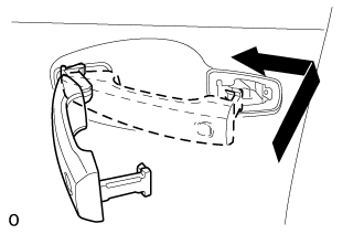 |
Using a T30 ''TORX'' socket, install the screw.
 |
Connect the connector.
| 2. INSTALL FRONT DOOR OUTSIDE HANDLE COVER LH |
Attach the 2 claws to install the front door outside handle cover LH to the front door lock cylinder.
 |
Using a T30 ''TORX'' socket, install the front door outside cover LH (with the door lock cylinder) with the screw.
- Torque:
- 4.0 N*m{41 kgf*cm, 35 in.*lbf}
Install the hole plug.
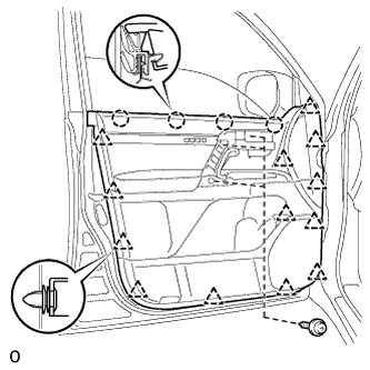
| 3. INSTALL FRONT DOOR SERVICE HOLE COVER LH |
Apply butyl tape to the door.
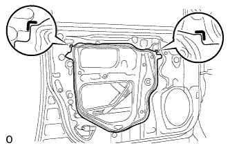 |
Pass the front door lock remote control cable assembly LH and front door inside locking cable assembly LH through a new front door service hole cover LH.
- NOTICE:
- When installing the front door service hole cover LH, pull the links and connectors through the front door service hole cover LH.
- There should be no wrinkles or folds after attaching the front door service hole cover LH.
- After attaching the front door service hole cover LH, check the sealing quality.
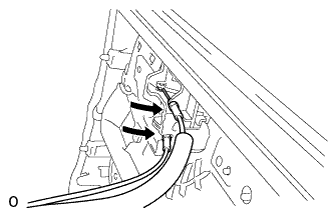
Connect the 2 connectors.
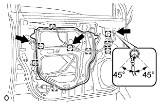 |
Attach the 9 clamps.
Install the bolt as shown in the illustration.
- Torque:
- 8.4 N*m{86 kgf*cm, 74 in.*lbf}
| 4. INSTALL FRONT DOOR TRIM BOARD SUB-ASSEMBLY LH |
Connect the connector.
 |
Connect the front door lock remote control cable assembly LH and front door inside locking cable assembly LH to the front door inside handle sub-assembly LH.
Attach the 4 claws and 13 clips to install the front door trim board sub-assembly LH.
 |
Install the 3 screws.
| 5. INSTALL COURTESY LIGHT ASSEMBLY (w/ Courtesy Light) |
Connect the connector.
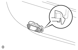 |
Attach the claw of the courtesy light to the front door trim.
| 6. INSTALL DOOR ASSIST GRIP COVER LH |
Attach the 8 claws to install the door assist grip cover LH to the front door trim board sub-assembly LH.
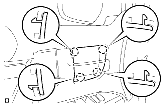
| 7. INSTALL FRONT DOOR INSIDE HANDLE BEZEL LH |
Attach the 4 claws to install the front door inside handle bezel LH.
 |
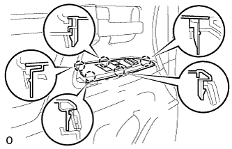
| 8. INSTALL FRONT DOOR ARMREST BASE PANEL ASSEMBLY LH |
Connect the connector.
Attach the 5 claws to install the armrest base panel.
 |
| 9. INSTALL FRONT LOWER DOOR FRAME BRACKET GARNISH LH |
Attach the clip and claw, and install the front door lower frame bracket garnish LH.
| 10. CONNECT CABLE TO NEGATIVE BATTERY TERMINAL |
- NOTICE:
- When disconnecting the cable, some systems need to be initialized after the cable is reconnected (Click here).
| 11. CHECK SRS WARNING LIGHT |
Check the SRS warning light (Click here).