Lighting System Headlight (Hi-Beam) Circuit
DESCRIPTION
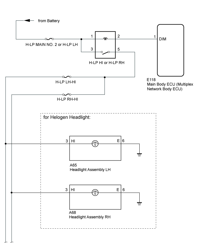
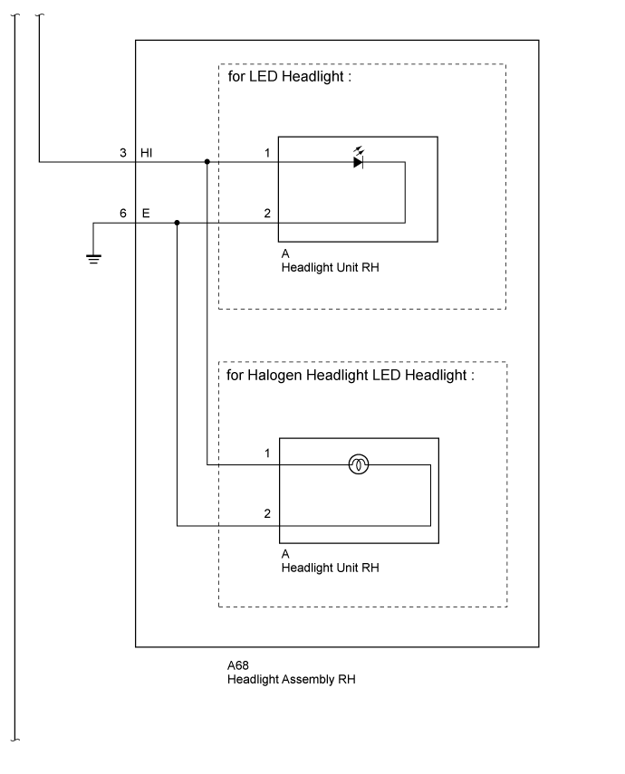
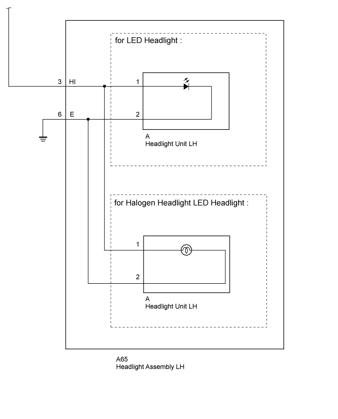
WIRING DIAGRAM
INSPECTION PROCEDURE
READ VALUE USING GTS (HEAD LIGHT SW [HEAD])
PERFORM ACTIVE TEST USING GTS (HEAD HI RELAY)
INSPECT HEADLIGHT RELAY (H-LP HI OR H-LP RH)
CHECK HARNESS AND CONNECTOR (BATTERY - HEADLIGHT RELAY [H-LP HI OR H-LP RH])
CHECK HARNESS AND CONNECTOR (HEADLIGHT RELAY [H-LP HI OR H-LP RH] - HEADLIGHT ASSEMBLY
CHECK HARNESS AND CONNECTOR (MAIN BODY ECU [MULTIPLEX
NETWORK BODY ECU] - HEADLIGHT RELAY [H-LP HI OR H-LP RH]
CHECK HARNESS AND CONNECTOR (HEADLIGHT RELAY [H-LP HI OR H-LP RH] - HEADLIGHT ASSEMBLY
INSPECT HEADLIGHT ASSEMBLY
LIGHTING SYSTEM - Headlight (HI-BEAM) Circuit |
DESCRIPTION
The main body ECU receives a headlight hi switch information signal from the light control switch, and illuminates the headlight high beam.
WIRING DIAGRAM
INSPECTION PROCEDURE
- NOTICE:
- Inspect the fuses and bulbs for circuits related to this system before performing the following inspection procedure.
| 1.READ VALUE USING GTS (HEAD LIGHT SW [HEAD]) |
Operate the GTS according to the display and select the Data List (Click here).
Main BodyTester Display
| Measurement Item/Range
| Normal Condition
| Diagnostic Note
|
Head Light SW (Head)
| Headlight switch signal / ON or OFF
| ON: Headlight switch (Head) on
OFF: Headlight switch (Head) off
| -
|
- OK:
- Normal conditions listed above are displayed.
| OK |
|
|
|
| PROCEED TO NEXT CIRCUIT INSPECTION SHOWN IN PROBLEM SYMPTOMS TABLE (Click here) |
|
| 2.PERFORM ACTIVE TEST USING GTS (HEAD HI RELAY) |
Using the GTS, perform the Active Test (Click here).
Main BodyTester Display
| Test Part
| Control Range
| Diagnostic Note
|
Head Light Hi
| Headlight (Hi)
| ON or OFF
| -
|
- OK:
- Headlight high beam turns on/turns off.
ResultResult
| Proceed to
|
Headlights (Both high beams turn on) (for LHD)
| A
|
Headlights (Both high beams turn on) (for RHD)
| B
|
Headlights (Neither high beam turns on)
| C
|
Headlight on one side (High beam does not turn on)
| D
|
Headlight on one side (High beam does not turn on) [for Halogen Headlight]
| E
|
| | REPLACE MAIN BODY ECU (MULTIPLEX NETWORK BODY ECU) (Click here) |
|
|
| |
|
| |
|
| |
|
| A |
|
|
|
| REPLACE MAIN BODY ECU (MULTIPLEX NETWORK BODY ECU) (Click here) |
|
| 3.INSPECT HEADLIGHT RELAY (H-LP HI OR H-LP RH) |
Remove the H-LP HI or H-LP RH relay from the engine room relay block, junction block.
Inspect the H-LP HI or H-LP RH relay (Click here).
| | REPLACE HEADLIGHT RELAY (H-LP HI OR H-LP RH) |
|
|
| 4.CHECK HARNESS AND CONNECTOR (BATTERY - HEADLIGHT RELAY [H-LP HI OR H-LP RH]) |
Remove the H-LP HI or H-LP RH relay from the engine room relay block, junction block.
Measure the voltage according to the value(s) in the table below.
- Standard Voltage:
Tester Connection
| Condition
| Specified Condition
|
Headlight relay terminal 1- Body ground
| Always
| 11 to 14 V
|
Headlight relay terminal 3 - Body ground
|
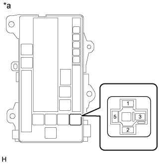
Text in Illustration*a
| Front view of wire harness connector
(to Headlight Relay [H-LP HI or H-LP RH])
|
| | REPAIR OR REPLACE HARNESS OR CONNECTOR |
|
|
| 5.CHECK HARNESS AND CONNECTOR (HEADLIGHT RELAY [H-LP HI OR H-LP RH] - HEADLIGHT ASSEMBLY |
Remove the H-LP HI or H-LP RH relay from the engine room relay block, junction block.
Disconnect the A65*1 or A68*2 headlight connector.
- *1: for LH
- *2: for RH
Measure the resistance according to the value(s) in the table below.
- Standard Resistance:
for LHTester Connection
| Condition
| Specified Condition
|
Headlight relay terminal 5 - A65-3 (HI)
| Always
| Below 1 Ω
|
Headlight relay terminal 5 - Body ground
| Always
| 10 kΩ or higher
|
for RHTester Connection
| Condition
| Specified Condition
|
Headlight relay terminal 5 - A68-3 (HI)
| Always
| Below 1 Ω
|
Headlight relay terminal 5 - Body ground
| Always
| 10 kΩ or higher
|
| | REPAIR OR REPLACE HARNESS OR CONNECTOR |
|
|
| 6.CHECK HARNESS AND CONNECTOR (MAIN BODY ECU [MULTIPLEX
NETWORK BODY ECU] - HEADLIGHT RELAY [H-LP HI OR H-LP RH] |
Remove the H-LP HI or H-LP RH relay from the engine room relay block, junction block.
Remove the cowl side junction block LH.
Disconnect the E118 main body ECU connector.
Measure the resistance according to the value(s) in the table below.
- Standard Resistance:
Tester Connection
| Condition
| Specified Condition
|
Headlight relay terminal 2 - E118-1 (DIM)
| Always
| Below 1 Ω
|
E118-1 (DIM) - Body ground
| Always
| 10 kΩ or higher
|
ResultResult
| Proceed to
|
OK (for LHD)
| A
|
OK (for RHD)
| B
|
NG
| C
|
| | REPLACE MAIN BODY ECU (MULTIPLEX NETWORK BODY ECU) (Click here) |
|
|
| | REPAIR OR REPLACE HARNESS OR CONNECTOR |
|
|
| A |
|
|
|
| REPLACE MAIN BODY ECU (MULTIPLEX NETWORK BODY ECU) (Click here) |
|
| 7.CHECK HARNESS AND CONNECTOR (HEADLIGHT RELAY [H-LP HI OR H-LP RH] - HEADLIGHT ASSEMBLY |
Remove the H-LP HI or H-LP RH relay from the engine room relay block, junction block.
Disconnect the A65*1 or A68*2 headlight connector.
- *1: for LH
- *2: for RH
Measure the resistance according to the value(s) in the table below.
- Standard Resistance:
for LHTester Connection
| Condition
| Specified Condition
|
Headlight relay terminal 5 - A65-3 (HI)
| Always
| Below 1 Ω
|
A65-6 (E) - Body ground
| Always
|
Headlight relay terminal 5 - Body ground
| Always
| 10 kΩ or higher
|
for RHTester Connection
| Condition
| Specified Condition
|
Headlight relay terminal 5 - A68-3 (HI)
| Always
| Below 1 Ω
|
A68-6 (E) - Body ground
| Always
|
Headlight relay terminal 5 - Body ground
| Always
| 10 kΩ or higher
|
| | REPAIR OR REPLACE HARNESS OR CONNECTOR |
|
|
| 8.INSPECT HEADLIGHT ASSEMBLY |
for LED Headlight
Remove the headlight assembly (Click here).
for Halogen Headlight and LED Headlight
Remove the headlight assembly (Click here).
for LED Headlight
Remove the headlight unit from the headlight assembly (Click here).
for Halogen Headlight and LED Headlight
Remove the headlight unit from the headlight assembly (Click here).
Measure the resistance according to the value(s) in the table below.
- Standard Resistance:
for LED HeadlightTester Connection
| Condition
| Specified Condition
|
A-3 (B) - B-1
| Always
| Below 1 Ω
|
A-6 (E) - B-2
| Always
| 10 kΩ or higher
|
for Halogen Headlight and LED HeadlightTester Connection
| Condition
| Specified Condition
|
A-3 (B) - B-1
| Always
| Below 1 Ω
|
A-6 (E) - B-2
| Always
| 10 kΩ or higher
|
ResultResult
| Proceed to
|
OK (for LED Headlight)
| A
|
OK (for Halogen Headlight and LED Headlight)
| B
|
NG (for LED Headlight)
| C
|
NG (for Halogen Headlight and LED Headlight)
| D
|