Lighting System Taillight Circuit
DESCRIPTION
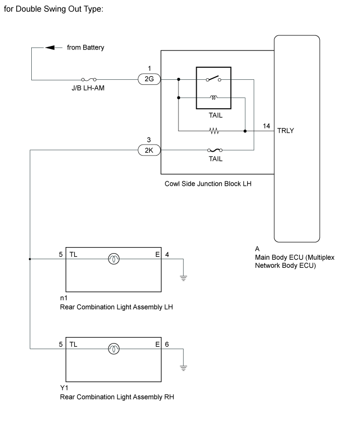
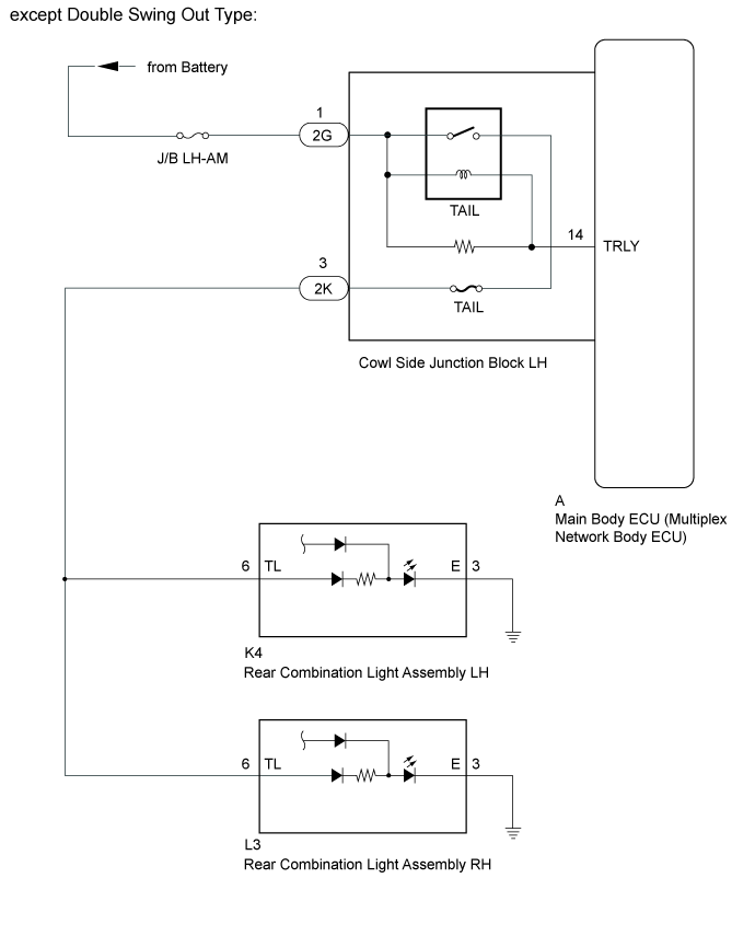
WIRING DIAGRAM
INSPECTION PROCEDURE
PERFORM ACTIVE TEST USING GTS (TAILLIGHT)
CHECK HARNESS AND CONNECTOR (COWL SIDE JUNCTION BLOCK LH - BATTERY)
CHECK HARNESS AND CONNECTOR (REAR COMBINATION LIGHT - COWL SIDE JUNCTION BLOCK LH
INSPECT COWL SIDE JUNCTION BLOCK LH
LIGHTING SYSTEM - Taillight Circuit |
DESCRIPTION
The main body ECU (multiplex network body ECU) receives a light control switch information signal from the headlight dimmer switch, and illuminates the taillights.
WIRING DIAGRAM
INSPECTION PROCEDURE
| 1.PERFORM ACTIVE TEST USING GTS (TAILLIGHT) |
Operate the GTS according to the steps on the display and select "Active Test" (Click here).
Main BodyTester Display
| Test Part
| Control Range
| Diagnostic Note
|
Taillight Relay
| Taillight
| ON or OFF
| -
|
- OK:
- Taillight turns on/turns off.
| OK |
|
|
|
| PROCEED TO NEXT SUSPECTED AREA SHOWN IN PROBLEM SYMPTOMS TABLE (Click here) |
|
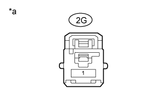
| 2.CHECK HARNESS AND CONNECTOR (COWL SIDE JUNCTION BLOCK LH - BATTERY) |
Disconnect the 2G cowl side junction block LH connector.
Measure the voltage according to the value(s) in the table below.
- Standard Voltage:
Tester Connection
| Condition
| Specified Condition
|
2G-1 - Body ground
| Always
| 11 to 14 V
|
Text in Illustration*a
| Front view of wire harness connector
(to Cowl Side Junction Block LH)
|
| | REPAIR OR REPLACE HARNESS OR CONNECTOR |
|
|
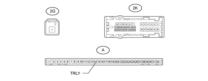
| 3.CHECK HARNESS AND CONNECTOR (REAR COMBINATION LIGHT - COWL SIDE JUNCTION BLOCK LH |
Disconnect the 2K cowl side junction block LH connector.
except Double Swing Out Type:
- Disconnect the K4*1 and L3*2 light connectors.
*1: for LH
*2: for RH
- Measure the resistance according to the value(s) in the table below.
- Standard Resistance:
- for LH:
Tester Connection
| Condition
| Specified Condition
|
2K-3 - K4-6 (TL)
| Always
| Below 1 Ω
|
K4-3 (E) - Body ground
|
K4-6 (TL) - Body ground
| Always
| 10 kΩ or higher
|
- for RH:
Tester Connection
| Condition
| Specified Condition
|
2K-3 - L3-6 (TL)
| Always
| Below 1 Ω
|
L3-3 (E) - Body ground
|
L3-6 (TL) - Body ground
| Always
| 10 kΩ or higher
|
for Double Swing Out Type:
- Disconnect the n1*1 and Y1*2 light connectors.
*1: for LH
*2: for RH
- Measure the resistance according to the value(s) in the table below.
- Standard Resistance:
- for LH:
Tester Connection
| Condition
| Specified Condition
|
2K-3 - n1-5 (TL)
| Always
| Below 1 Ω
|
n1-4 (E) - Body ground
|
n1-5 (TL) - Body ground
| Always
| 10 kΩ or higher
|
- for RH:
Tester Connection
| Condition
| Specified Condition
|
2K-3 - Y1-5 (TL)
| Always
| Below 1 Ω
|
Y1-6 (E) - Body ground
|
Y1-5 (TL) - Body ground
| Always
| 10 kΩ or higher
|
| | REPAIR OR REPLACE HARNESS OR CONNECTOR |
|
|
| 4.INSPECT COWL SIDE JUNCTION BLOCK LH |
for LHD:
Remove the cowl side junction block LH (Click here).
Remove the main body ECU (multiplex network body ECU) from the cowl side junction block LH (Click here).
for RHD:
Remove the cowl side junction block LH (Click here).
Remove the main body ECU (multiplex network body ECU) from the cowl side junction block LH (Click here).
Measure the voltage according to the value(s) in the table below.
- Standard Voltage:
Tester Connection
| Condition
| Specified Condition
|
2K-3 - Battery negative (-) terminal
| Battery voltage applied between terminals 2G-1 and A-14 (TRLY)
| 11 to 14 V
|
Battery voltage not applied between terminals 2G-1 and A-14 (TRLY)
| Below 1 V
|
ResultResult
| Proceed to
|
OK (for LHD)
| A
|
OK (for RHD)
| B
|
NG (for LHD)
| C
|
NG (for RHD)
| D
|
| | REPLACE MAIN BODY ECU (MULTIPLEX NETWORK BODY ECU) (Click here) |
|
|
| |
|
| |
|
| A |
|
|
|
| REPLACE MAIN BODY ECU (MULTIPLEX NETWORK BODY ECU) (Click here) |
|