Lighting System -- Terminals Of Ecu |
| CHECK MAIN BODY ECU (COWL SIDE JUNCTION BLOCK LH) |

Disconnect the E1, E2, E3, 2A, 2B, 2C, and 2D ECU connectors.
Measure the voltage and resistance according to the value(s) in the table below.
Terminal No. (Symbol) Wiring Color Terminal Description Condition Specified Condition 2A-1 - Body ground B - Body ground Battery power supply Always 11 to 14 V 2D-62 (GND2) - Body ground W-B - Body ground Body ground Always Below 1 Ω 2D-62 (GND1) - Body ground*1 W-B - Body ground Body ground Always Below 1 Ω E1-24 (DCTY) - Body ground*2 L - Body ground Front door courtesy light switch LH signal Front door LH open Below 1 Ω E1-24 (DCTY) - Body ground*2 L - Body ground Front door courtesy light switch LH signal Front door LH closed 10 kΩ or higher E1-24 (DCTY) - Body ground*3 P - Body ground Front door courtesy light switch LH signal Front door LH open Below 1 Ω E1-24 (DCTY) - Body ground*3 P - Body ground Front door courtesy light switch LH signal Front door LH closed 10 kΩ or higher E2-21 (PCTY) - Body ground*2 P - Body ground Front door courtesy light switch RH signal Front door RH open Below 1 Ω E2-21 (PCTY) - Body ground*2 P - Body ground Front door courtesy light switch RH signal Front door RH closed 10 kΩ or higher E2-21 (PCTY) - Body ground*3 L - Body ground Front door courtesy light switch RH signal Front door RH open Below 1 Ω E2-21 (PCTY) - Body ground*3 L - Body ground Front door courtesy light switch RH signal Front door RH closed 10 kΩ or higher 2C-2 (LCTY) - Body ground W - Body ground Rear door courtesy light switch LH signal Rear door LH open Below 1 Ω 2C-2 (LCTY) - Body ground W - Body ground Rear door courtesy light switch LH signal Rear door LH closed 10 kΩ or higher E2-7 (RCTY) - Body ground*1 G - Body ground Rear door courtesy light switch RH signal Rear door RH open Below 1 Ω E2-7 (RCTY) - Body ground*1 G - Body ground Rear door courtesy light switch RH signal Rear door RH closed 10 kΩ or higher E1-17 (RCTY) - Body ground*4 G - Body ground Rear door courtesy light switch RH signal Rear door RH open Below 1 Ω E1-17 (RCTY) - Body ground*4 G - Body ground Rear door courtesy light switch RH signal Rear door RH closed 10 kΩ or higher E2-25 (BCTY) - Body ground W - Body ground Back door courtesy light switch signal Back door open Below 1 Ω E2-25 (BCTY) - Body ground W - Body ground Back door courtesy light switch signal Back door closed 10 kΩ or higher E1-23 (TAIL) - Body ground V - Body ground Light control switch TAIL signal Light control switch tail Below 1 Ω E1-23 (TAIL) - Body ground V - Body ground Light control switch TAIL signal Light control switch except tail 10 kΩ or higher E2-17 (HEAD) - Body ground R- Body ground Light control switch HEAD signal Light control switch head Below 1 Ω E2-17 (HEAD) - Body ground R - Body ground Light control switch HEAD signal Light control switch except head 10 kΩ or higher E1-21 (A) - Body ground G - Body ground Light control switch AUTO signal Light control switch auto Below 1 Ω E1-21 (A) - Body ground G - Body ground Light control switch AUTO signal Light control switch except auto 10 kΩ or higher E2-28 (FFOG) - Body ground*5 R - Body ground Front fog light switch signal Front fog light switch on Below 1 Ω E2-28 (FFOG) - Body ground*5 R - Body ground Front fog light switch signal Front fog light switch off 10 kΩ or higher E2-9 (RFOG) - Body ground*6 R - Body ground Rear fog light switch signal Rear fog light switch on Below 1 Ω E2-9 (RFOG) - Body ground*6 R - Body ground Rear fog light switch signal Rear fog light switch off 10 kΩ or higher 2D-13 (HU) - Body ground R - Body ground Dimmer switch high signal Dimmer switch high Below 1 Ω 2D-13 (HU) - Body ground R - Body ground Dimmer switch high signal Dimmer switch except high or flash 10 kΩ or higher E1-13 (HF) - Body ground GR - Body ground Dimmer switch flash signal Dimmer switch flash Below 1 Ω E1-13 (HF) - Body ground GR - Body ground Dimmer switch flash signal Dimmer switch except flash 10 kΩ or higher 2D-51 (ILE) - Body ground G - Body ground Interior light signal Map light on Below 1 Ω 2D-51 (ILE) - Body ground G - Body ground Interior light signal Map light off 10 kΩ or higher - *1: w/o Entry and Start System
- *2: for LHD
- *3: for RHD
- *4: w/ Entry and Start System
- *5: w/ Front Fog Light
- *6: w/ Rear Fog Light
- *1: w/o Entry and Start System
Reconnect the E1, E2, E3, 2A, 2B, 2C, and 2D ECU connectors.
Measure the voltage according to the value(s) in the table below.
Terminal No. (Symbol) Wiring Color Terminal Description Condition Specified Condition E1-4 (FFGO) - Body ground*1 R - Body ground Front fog light signal Light control switch tail,
front fog light switch onBelow 1 V E1-4 (FFGO) - Body ground*1 R - Body ground Front fog light signal Light control switch tail,
front fog light switch off11 to 14 V E2-8 (DRLE) - Body ground*2, *3 R - Body ground Daytime running light signal Daytime running light on Below 1 V E2-8 (DRLE) - Body ground*2, *3 R - Body ground Daytime running light signal Daytime running light off 11 to 14 V E3-14 (DRLE) - Body ground*2, *4 R - Body ground Daytime running light signal Daytime running light on Below 1 V E3-14 (DRLE) - Body ground*2, *4 R - Body ground Daytime running light signal Daytime running light on 11 to 14 V E2-15 (DIM) - Body ground*5 L - Body ground Headlight high beam signal Light control switch head,
dimmer switch highBelow 1 V E2-15 (DIM) - Body ground*5 L - Body ground Headlight high beam signal Light control switch head,
dimmer switch except high11 to 14 V E3-14 (RFGO) - Body ground*6 R - Body ground Rear fog light signal Light control switch tail,
rear fog light switch offBelow 1 V E3-14 (RFGO) - Body ground*6 R - Body ground Rear fog light signal Light control switch tail,
rear fog light switch off11 to 14 V 2B-18 (HRLY) - Body ground L - Body ground Headlight low beam signal Light control switch head,
dimmer switch lowBelow 1 V 2B-18 (HRLY) - Body ground L - Body ground Headlight low beam signal Light control switch head,
dimmer switch except low11 to 14 V 2B-16 (DIM) - Body ground*7 LG - Body ground Headlight high beam signal Light control switch head,
dimmer switch highBelow 1 V 2B-16 (DIM) - Body ground*7 LG - Body ground Headlight high beam signal Light control switch head,
dimmer switch except high11 to 14 V 2B-22 (STP) - Body ground R - Body ground Stop light switch signal Brake pedal depressed 11 to 14 V 2B-22 (STP) - Body ground R - Body ground Stop light switch signal Brake pedal released Below 1 V 2D-29 (DOMR) - Body ground*8 R - Body ground Battery save system (interior light auto cut function) signal Battery save system (interior light auto cut function) operating 11 to 14 V 2D-29 (DOMR) - Body ground*8 R - Body ground Battery save system (interior light auto cut function) signal Battery save system (interior light auto cut function) not operating Below 1 V - *1: w/ Front Fog Light
- *2: w/ Daytime Running Light
- *3: except G. C. C.
- *4: for G. C. C.
- *5: except Double Swing Out Type
- *6: w/ Rear Fog Light
- *7: for Double Swing Out Type
- *8: w/ Dome Cut Relay
- *1: w/ Front Fog Light
| CHECK HEADLIGHT LEVELING ECU ASSEMBLY (w/ Static Headlight Auto Leveling) |

Disconnect the E109 headlight leveling ECU connector.
Measure the voltage and resistance according to the value(s) in the table below.
If the result is not as specified, there may be a malfunction on the wire harness side.Terminal No. (Symbol) Wiring Color Terminal Description Condition Specified Condition E109-1 (IG) - Body ground R - Body ground Ignition power supply Ignition switch off Below 1 V Ignition switch ON 11 to 14 V E109-9 (E1) - Body ground W-B - Body ground Ground Always Below 1 Ω Reconnect the E109 headlight leveling ECU connector.
Measure the voltage and resistance according to the value(s) in the table below.
Terminal No. (Symbol) Wiring Color Terminal Description Condition Specified Condition E109-3 (HDLP) - E109-9 (E1) L - W-B Low beam headlight signal input Low beam headlights on Below 1 V Low beam headlights off 11 to 14 V E109-5 (INIT) - E109-9 (E1) LG - W-B Initialization signal input Terminal LVL and terminal CG of DLC3 connected Below 1 V Terminal LVL and terminal CG of DLC3 not connected 4.5 to 5.5 V E109-6 (WNG) - E109-9 (E1) L - W-B Warning indicator drive output Warning indicator on Below 1 V Warning indicator off 11 to 14 V E109-10 (RH+) - E109-9 (E1) G - W-B Headlight leveling motor RH power supply Ignition switch off Below 1 V Ignition switch ON 11 to 14 V E109-11 (LH+) - E109-9 (E1) R - W-B Headlight leveling motor LH power supply Ignition switch off Below 1 V Ignition switch ON 11 to 14 V E109-12 (SBR) - E109-21 (SGR) L - P Rear height control sensor power supply Ignition switch off Below 1 V Ignition switch ON 4.75 to 5.25 V E109-16 (SPDR) - E109-9 (E1) V - W-B Vehicle speed signal input Vehicle is driven at approximately 20 km/h (12 mph) Pulse generation
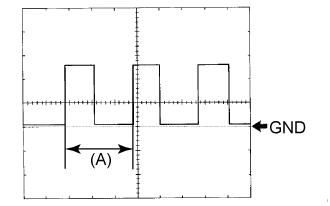
(See waveform 1)E109-17 (RHT) - E109-9 (E1) P - W-B Headlight leveling motor RH operation signal input With low beam headlights on, vehicle height not changed Below 1 V With low beam headlights on, vehicle height changed and maintained for more than 3 seconds 1.0 to 14.4 V E109-18 (LHT) - E109-9 (E1) G - W-B Headlight leveling motor LH operation signal input With low beam headlights on, vehicle height not changed Below 1 V With low beam headlights on, vehicle height changed and maintained for more than 3 seconds 1.0 to 14.4 V E109-19 (SHRL) - E109-21 (SGR) SB - P Rear height control sensor signal input Ignition switch off Below 1 V Ignition switch ON 0.5 to 4.5 V E109-21 (SGR) - E109-9 (E1) P - W-B Rear height control sensor ground Always Below 1 Ω E109-23 (RH-) - E109-9 (E1) BR - W-B Headlight leveling motor RH ground Always Below 1 Ω E109-24 (LH-) - E109-9 (E1) V - W-B Headlight leveling motor LH ground Always Below 1 Ω Waveform 1
Item Content Terminal No. (Symbol) E109-16 (SPDR) - E109-9 (E1) Tool setting 5 V/DIV., 20 ms./DIV. Condition Vehicle is driven at approximately 20 km/h (12 mph) - HINT:
- When the system is functioning normally, one wheel revolution generates 4 pulses. As the vehicle speed increases, the width indicated by (A) in the illustration narrows.
| CHECK HEADLIGHT SWIVEL ECU ASSEMBLY (w/ Dynamic Headlight Auto Leveling) |

Disconnect the E101 headlight swivel ECU connector.
Measure the voltage and resistance according to the value(s) in the table below.
If the result is not as specified, there may be a malfunction on the wire harness side.Terminal No. (Symbol) Wiring Color Terminal Description Condition Specified Condition E101-15 (IG) - Body ground R - Body ground Ignition power supply Ignition switch off Below 1 V Ignition switch ON 11 to 14 V E101-22 (E1) - Body ground W-B - Body ground Ground Always Below 1 Ω Reconnect the E101 headlight swivel ECU connector.
Measure the voltage and resistance according to the value(s) in the table below.
Terminal No. (Symbol) Wiring Color Terminal Description Condition Specified Condition E101-3 (LHT) - E101-22 (E1) R - W-B Headlight leveling motor LH power supply Ignition switch off Below 1 V Ignition switch ON 11 to 14 V E101-4 (RHT) - E101-22 (E1) G - W-B Headlight leveling motor RH power supply Ignition switch off Below 1 V Ignition switch ON 11 to 14 V E101-7 (INIT) - E101-22 (E1) LG - W-B Initialization signal Ignition switch ON, terminals LVL and GND of DLC3 connected Below 1 V Ignition switch ON, terminals LVL and GND of DLC3 not connected 4.5 to 5.5 V E101-11 (RH+) - E101-22 (E1) P - W-B Headlight leveling motor RH LIN communication Ignition switch off Below 1 V Ignition switch ON Pulse generation E101-17 (SHFL) - E101-22 (E1)*1 GR - W-B Vehicle height signal Ignition switch off Below 1 V Ignition switch ON Approximately 2.5 V (When vehicle level)
(The value changes according to the vehicle height)E101-18 (SBR) - E101-22 (E1)*1 L - W-B Vehicle height signal Ignition switch off Below 1 V Ignition switch ON 4.5 to 5.5 V E101-18 (SBR) - E101-21 (SGR)*2 L - P Rear height control sensor LH power supply Ignition switch off Below 1 V Ignition switch ON 4.5 to 5.5 V E101-19 (SHRL) - E101-22 (E1)*1 SB - W-B Vehicle height signal Ignition switch off Below 1 V Ignition switch ON Approximately 2.5 V (When vehicle level)
(The value changes according to the vehicle height)E101-19 (SHRL) - E101-21 (SGR)*2 SB - P Rear height control sensor LH signal Ignition switch off Below 1 V Ignition switch ON Approximately 2.5 V (When vehicle level)
(The value changes according to the vehicle height)E101-21 (SGR) - E101-22 (E1)*1 P - W-B Vehicle height signal Always Below 1 Ω E101-21 (SGR) - E101-22 (E1)*2 P - W-B Rear height control sensor LH ground Always Below 1 Ω E101-27 (LH-) - E101-22 (E1) V - W-B Headlight leveling motor LH ground Always Below 1 Ω E101-28 (RH-) - E101-22 (E1) BR - W-B Headlight leveling motor RH ground Always Below 1 Ω E101-30 (LH+) - E101-22 (E1) G - W-B Headlight leveling motor LH LIN communication Ignition switch off Below 1 V Ignition switch ON Pulse generation - *1: w/ Active Height Control Suspension
- *2: w/o Active Height Control Suspension
- *1: w/ Active Height Control Suspension
| CHECK NO. 2 MAIN BODY ECU (w/ Side Step Light) |
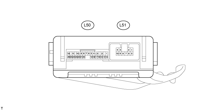
Disconnect the L50 and L51 ECU connectors.
Measure the voltage and resistance according to the value(s) in the table below.
Terminal No. (Symbol) Wiring Color Terminal Description Condition Specified Condition L50-14 (BECU) - Body ground R - Body ground Battery power supply Always 11 to 14 V L50-13 (SIG) - Body ground G - Body ground Ignition power supply Ignition switch off Below 1 V Ignition switch ON 11 to 14 V L50-7 (GND) - Body ground W-B - Body ground Ground Always Below 1 Ω L51-7 (GND) - Body ground W-B - Body ground Ground Always Below 1 Ω - If the result is not as specified, there may be a malfunction on the wire harness side.
- If the result is not as specified, there may be a malfunction on the wire harness side.
Reconnect the L50 and L51 ECU connectors.
Measure the voltage according to the value(s) in the table below.
Terminal No. (Symbol) Wiring Color Terminal Description Condition Specified Condition L50-9 (RBD1) - Body ground L - Body ground Step light LH signal Step light LH on Below 1 V Step light LH off 11 to 14 V L50-21 (RBD2) - Body ground L - Body ground Step light RH signal Step light RH on Below 1 V Step light RH off 11 to 14 V
| CHECK INNER REAR VIEW MIRROR ASSEMBLY (w/ Automatic High Beam System) |

Disconnect the R16 mirror connector.
Measure the voltage and resistance according to the value(s) in the table below.
If the result is not as specified, there may be a malfunction on the wire harness side.Terminal No. (Symbol) Wiring Color Terminal Description Condition Specified Condition R16-1 (IG) - Body ground G - Body ground IG power supply Ignition switch ON 11 to 14 V R16-2 (E) - Body ground W-B - Body ground Ground Always Below 1 Ω Reconnect the R16 mirror connector.
Measure the voltage according to the value(s) in the table below.
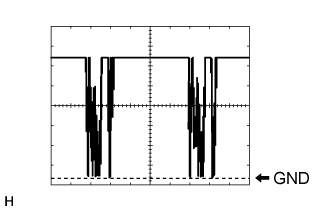
Terminal No. (Symbol) Wiring Color Terminal Description Condition Specified Condition R16-10 (LIN) - R16-2 (E) B - W-B LIN communication Automatic high beam system operates Pulse generation (See waveform 1) Waveform 1
Item Content Terminal No. (Symbol) R16-10 (LIN) - R16-2 (E) Tool setting 2 V/DIV., 20 ms./DIV. Condition Automatic high beam system operates