CHECK HARNESS AND CONNECTOR (MAIN BODY ECU - MASTER SWITCH)
CHECK HARNESS AND CONNECTOR (COWL SIDE JUNCTION BLOCK LH - MASTER SWITCH)
DTC B2325 LIN Communication Bus Malfunction |
DESCRIPTION
The main body ECU (multiplex network body ECU) intermittently monitors the LIN communication bus between the components related to the door and sliding roof. DTC B2325 is stored when a malfunction in the LIN communication bus between the components related to the door and sliding roof is detected consecutively 3 times.| DTC Code | DTC Detection Condition | Trouble Area |
| B2325 | The main body ECU (multiplex network body ECU) detects a malfunction in the LIN communication bus between components related to the doors and sliding roof consecutively 3 times. | for LHD:
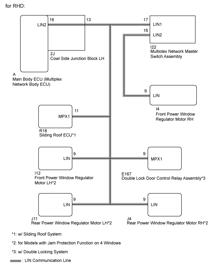
for RHD:
|
- *1: for Models with Jam Protection Function on 4 Windows
- *2: w/ Sliding Roof System
- *3: w/ Double Locking System
WIRING DIAGRAM

INSPECTION PROCEDURE
- NOTICE:
- When using the GTS with the ignition switch off to troubleshoot:
- Connect the GTS to the vehicle, and turn a courtesy switch on and off at 1.5 second intervals until communication between the GTS and vehicle begins.
- HINT:
- When DTC B2325 and a LIN communication stop DTC are output simultaneously, first perform the troubleshooting for the LIN communication stop DTC. Then perform the troubleshooting for DTC B2325.
| 1.CLEAR DTC |
Clear the DTC (Click here).
| NEXT | |
| 2.CHECK FOR DTC |
Recheck for DTCs (Click here).
Result Result Proceed to DTC B2325 is output A DTC B2325 is not output B
|
| ||||
| A | |
| 3.CHECK HARNESS AND CONNECTOR (MAIN BODY ECU - MASTER SWITCH) |
- *1: w/ Sliding Roof System
- *2: for Models with Jam Protection Function on 4 Windows
- *3: w/ Double Locking System
for LHD:
Disconnect the A main body ECU connector.
Disconnect the R18 sliding roof ECU connector*1.
Disconnect the I12 power window regulator motor connector.
Disconnect the I4, J4 and J11 power window regulator motor connectors*2.
Disconnect the I11 master switch connector.
Disconnect the E167 double lock door control relay connector*3.
Measure the resistance according to the value(s) in the tables below.
- Standard Resistance:
Tester Connection Condition Specified Condition A-16 (LIN2) - I11-17 (LIN1) Always Below 1 Ω A-16 (LIN2) - Body ground Always 10 kΩ or higher
for RHD:
Disconnect the A main body ECU connector.
Disconnect the R18 sliding roof ECU connector*1.
Disconnect the I4 power window regulator motor connector.
Disconnect the I12, J4 and J11 power window regulator motor connectors*2.
Disconnect the I22 master switch connector.
Disconnect the E167 double lock door control relay connector*3.
Measure the resistance according to the value(s) in the tables below.
- Standard Resistance:
Tester Connection Condition Specified Condition A-16 (LIN2) - I22-17 (LIN1) Always Below 1 Ω A-16 (LIN2) - Body ground Always 10 kΩ or higher
|
| ||||
| OK | |
| 4.CLEAR DTC |
- *1: w/ Sliding Roof System
- *2: for Models with Jam Protection Function on 4 Windows
- *3: w/ Double Locking System
for LHD:
Reconnect the A main body ECU connector.
Reconnect the R18 sliding roof ECU connector*1.
Reconnect the I12 power window regulator motor connector.
Reconnect the I4, J4 and J11 power window regulator motor connectors*2.
Disconnect the I11 master switch connector.
Reconnect the E167 double lock door control relay connector*3.
for RHD:
Reconnect the A main body ECU connector.
Reconnect the R18 sliding roof ECU connector*1.
Reconnect the I4 power window regulator motor connector.
Reconnect the I12, J4 and J11 power window regulator motor connectors*2.
Disconnect the I22 master switch connector.
Reconnect the E167 double lock door control relay connector*3.
Clear the DTC (Click here).
| NEXT | |
| 5.CHECK FOR DTC |
Recheck for DTCs (Click here).
Result Result Proceed to DTC B2325 is output A DTC B2325 is not output B
|
| ||||
| A | |
| 6.CLEAR DTC |
for LHD:
Reconnect the I11 master switch connector.
Disconnect the I12 power window regulator motor connector.
for LHD:
Reconnect the I22 master switch connector.
Disconnect the I4 power window regulator motor connector.
Clear the DTC (Click here).
| NEXT | |
| 7.CHECK FOR DTC |
Recheck for DTCs (Click here).
Result Result Proceed to DTC B2325 is output A DTC B2325 is not output (for LHD) B DTC B2325 is not output (for RHD) C
|
| ||||
|
| ||||
| A | |
| 8.CLEAR DTC |
- *: for Models with Jam Protection Function on 4 Windows
for LHD:
Reconnect the I12 power window regulator motor connector.
Disconnect the I4 power window regulator motor connector*.
for LHD:
Reconnect the I4 power window regulator motor connector.
Disconnect the I12 power window regulator motor connector*.
Clear the DTC (Click here).
| NEXT | |
| 9.CHECK FOR DTC |
Recheck for DTCs (Click here).
Result Result Proceed to DTC B2325 is output A DTC B2325 is not output (for LHD) B DTC B2325 is not output (for RHD) C
|
| ||||
|
| ||||
| A | |
| 10.CLEAR DTC |
- *: for Models with Jam Protection Function on 4 Windows
for LHD:
Reconnect the I4 power window regulator motor connector*.
Disconnect the J4 power window regulator motor connector*.
for LHD:
Reconnect the I12 power window regulator motor connector*.
Disconnect the J4 power window regulator motor connector*.
Clear the DTC (Click here).
| NEXT | |
| 11.CHECK FOR DTC |
Recheck for DTCs (Click here).
Result Result Proceed to DTC B2325 is output A DTC B2325 is not output B
|
| ||||
| A | |
| 12.CLEAR DTC |
- *: for Models with Jam Protection Function on 4 Windows
Reconnect the J4 power window regulator motor connector*.
Disconnect the J11 power window regulator motor connector*.
Clear the DTC (Click here).
| NEXT | |
| 13.CHECK FOR DTC |
Recheck for DTCs (Click here).
Result Result Proceed to DTC B2325 is output A DTC B2325 is not output B
|
| ||||
| A | |
| 14.CLEAR DTC |
- *1: for Models with Jam Protection Function on 4 Windows
- *2: w/ Double Locking System
Reconnect the J11 power window regulator motor connector*1.
Disconnect the E167 double lock door control relay connector*2.
Clear the DTC (Click here).
| NEXT | |
| 15.CHECK FOR DTC |
Recheck for DTC (Click here).
Result Result Proceed to DTC B2325 is output A DTC B2325 is not output (for LHD) B DTC B2325 is not output (for RHD) C
|
| ||||
|
| ||||
| A | |
| 16.CLEAR DTC |
- *1: w/ Double Locking System
- *2: w/ Sliding Roof System
Reconnect the J11 power window regulator motor connector*1.
Disconnect the R18 sliding roof ECU connector*2.
Clear the DTC (Click here).
| NEXT | |
| 17.CHECK FOR DTC |
Recheck for DTCs (Click here).
Result Result Proceed to DTC B2325 is output (for LHD) A DTC B2325 is output (for RHD) B DTC B2325 is not output C
|
| ||||
|
| ||||
| A | ||
| ||
| 18.CHECK HARNESS AND CONNECTOR (COWL SIDE JUNCTION BLOCK LH - MASTER SWITCH) |
- *1: w/ Sliding Roof System
- *2: for Models with Jam Protection Function on 4 Windows
- *3: w/ Double Locking System
for LHD:
Disconnect the 2J cowl side junction block LH connector.
Disconnect the R18 sliding roof ECU connector*1.
Disconnect the I12 power window regulator motor connector.
Disconnect the I4, J4 and J11 power window regulator motor connectors*2.
Disconnect the I11 master switch connector.
Disconnect the E167 double lock door control relay connector*3.
Measure the resistance according to the value(s) in the tables below.
- Standard Resistance:
Tester Connection Condition Specified Condition 2J-13 - I11-17 (LIN1) Always Below 1 Ω 2J-13 - Body ground Always 10 kΩ or higher
for RHD:
Disconnect the 2J cowl side junction block LH connector.
Disconnect the R18 sliding roof ECU connector*1.
Disconnect the I4 power window regulator motor connector.
Disconnect the I12, J4 and J11 power window regulator motor connectors*2.
Disconnect the I22 master switch connector.
Disconnect the E167 double lock door control relay connector*3.
Measure the resistance according to the value(s) in the tables below.
- Standard Resistance:
Tester Connection Condition Specified Condition 2J-13 - I22-17 (LIN1) Always Below 1 Ω 2J-13 - Body ground Always 10 kΩ or higher
| Result | Proceed to |
| OK (for LHD) | A |
| OK (for RHD) | B |
| NG | C |
|
| ||||
|
| ||||
| A | ||
| ||