Dtc B1500 Fuel Sender Open Detected
DESCRIPTION
WIRING DIAGRAM
INSPECTION PROCEDURE
READ VALUE USING INTELLIGENT TESTER (FUEL SENDER GAUGE)
CHECK HARNESS AND CONNECTOR (COMBINATION METER - PUMP AND GAUGE AND BODY GROUND)
INSPECT FUEL SUCTION WITH PUMP AND GAUGE TUBE ASSEMBLY
INSPECT FUEL SENDER GAUGE ASSEMBLY
CHECK COMBINATION METER TYPE
DTC B1500 Fuel Sender Open Detected |
DESCRIPTION
This DTC is output when the combination meter detects a fuel sender gauge malfunction via the CAN.DTC Code
| DTC Detection Condition
| Trouble Area
|
B1500
| When the combination meter detects a fuel sender gauge malfunction.
| - Harness or connector
- Combination meter assembly
- Fuel suction with pump and gauge tube assembly
- Fuel sender gauge assembly
|
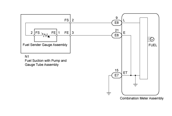
WIRING DIAGRAM
INSPECTION PROCEDURE
| 1.READ VALUE USING INTELLIGENT TESTER (FUEL SENDER GAUGE) |
Operate the intelligent tester according to the display and select the Data List (Click here).
Combination MeterTester Display
| Measurement Item/Range
| Normal Condition
| Diagnostic Note
|
Fuel Input
| Fuel sender gauge (main) input signal/Min.: 0, Max.: 127.5
| Fuel sender input value
| Unit: L
|
- OK:
- Fuel value displayed on the intelligent tester is almost the same as needle indication.
ResultResult
| Proceed to
|
NG
| A
|
OK (w/ Multi-information Display)
| B
|
OK (w/o Multi-information Display)
| C
|
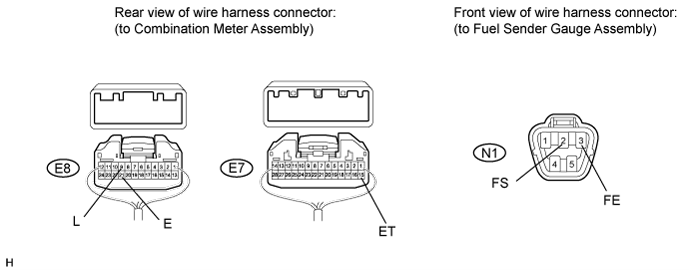
| 2.CHECK HARNESS AND CONNECTOR (COMBINATION METER - PUMP AND GAUGE AND BODY GROUND) |
Disconnect the E7 and E8 combination meter assembly connectors.
Disconnect the N1 fuel suction with pump and gauge tube assembly connector.
Measure the resistance according to the value(s) in the table below.
- Standard Resistance:
Tester Connection
| Condition
| Specified Condition
|
E8-9 (L) - N1-2 (FS)
| Always
| Below 1 Ω
|
E8-21 (E) - N1-3 (FE)
| Always
| Below 1 Ω
|
E7-15 (ET) - Body ground
| Always
| Below 1 Ω
|
E8-9 (L) or N1-2 (FS) - Body ground
| Always
| 10 kΩ or higher
|
| | REPAIR OR REPLACE HARNESS OR CONNECTOR |
|
|
| 3.INSPECT FUEL SUCTION WITH PUMP AND GAUGE TUBE ASSEMBLY |
Remove the fuel sender gauge assembly.
- HINT:
- for 1GR-FE (Click here)
- for 1UR-FE (Click here)
- for 3UR-FE (Click here)
- for 1VD-FTV (Click here)
Measure the resistance according to the value(s) in the table below.
- Standard Resistance:
Tester Connection
| Condition
| Specified Condition
|
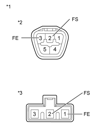
A-2 (FS) - B-2 (FS)
| Always
| Below 1 Ω
|
A-3 (FE) - B-1 (FE)
| Always
| Below 1 Ω
|
Text in Illustration*1
| Component without harness connected
(Fuel Suction with Pump and Gauge Tube Assembly)
|
*2
| Connector A
|
*3
| Connector B
|
ResultResult
| Proceed to
|
OK
| A
|
NG (for 1GR-FE)
| B
|
NG (for 1UR-FE)
| C
|
NG (for 3UR-FE)
| D
|
NG (for 1VD-FTV)
| E
|
| | REPLACE FUEL SUCTION WITH PUMP AND GAUGE TUBE ASSEMBLY (Click here) |
|
|
| | REPLACE FUEL SUCTION WITH PUMP AND GAUGE TUBE ASSEMBLY (Click here) |
|
|
| | REPLACE FUEL SUCTION WITH PUMP AND GAUGE TUBE ASSEMBLY (Click here) |
|
|
| | REPLACE FUEL SUCTION WITH PUMP AND GAUGE TUBE ASSEMBLY (Click here) |
|
|
| 4.INSPECT FUEL SENDER GAUGE ASSEMBLY |
Remove the fuel sender gauge assembly.
- HINT:
- for 1GR-FE (Click here)
- for 1UR-FE (Click here)
- for 3UR-FE (Click here)
- for 1VD-FTV (Click here)
Measure the resistance according to the value(s) in the table below.
- Standard Resistance:
Tester Connection
| Condition
| Specified Condition
|
2 (FS) - 1 (FE)
| Float level is F (upper)
| 13.5 to 16.5 Ω
|
Float level is E (lower)
| 405.5 to 414.5 Ω
|
Text in Illustration*1
| Component without harness connected
(Fuel Sender Gauge Assembly)
|
ResultResult
| Proceed to
|
OK
| A
|
NG (for 1GR-FE)
| B
|
NG (for 1UR-FE)
| C
|
NG (for 3UR-FE)
| D
|
NG (for 1VD-FTV)
| E
|
| 5.CHECK COMBINATION METER TYPE |
Check the combination meter type
ResultResult
| Proceed to
|
w/ Multi-information Display
| A
|
w/o Multi-information Display
| B
|