INSTALL LOWER INSTRUMENT PANEL PAD SUB-ASSEMBLY RH (for Double Swing Out Type Back Door)
INSTALL LOWER INSTRUMENT PANEL PAD SUB-ASSEMBLY LH (except Double Swing Out Type Back Door)
INSTALL NO. 1 INSTRUMENT PANEL FINISH CUSHION (for Double Swing Out Type Back Door)
INSTALL NO. 2 INSTRUMENT PANEL FINISH PANEL CUSHION (except Double Swing Out Type Back Door)
INSTALL COWL SIDE TRIM BOARD RH (for Double Swing Out Type Back Door)
INSTALL COWL SIDE TRIM BOARD LH (except Double Swing Out Type Back Door)
INSTALL FRONT DOOR SCUFF PLATE RH (for Double Swing Out Type Back Door)
INSTALL FRONT DOOR SCUFF PLATE LH (except Double Swing Out Type Back Door)
INSTALL INSTRUMENT SIDE PANEL RH (for Double Swing Out Type Back Door)
INSTALL INSTRUMENT SIDE PANEL LH (except Double Swing Out Type Back Door)
Knee Airbag Assembly (For Driver Side) -- Installation |
- HINT:
- Use the same procedure for RHD and LHD vehicles.
- The procedure listed below is for LHD vehicles.
| 1. INSTALL DRIVER SIDE KNEE AIRBAG ASSEMBLY |
Check that the ignition switch is off.
Check that the cable is disconnected from the negative (-) battery terminal.
- CAUTION:
- Wait at least 90 seconds after disconnecting the cable from the negative (-) battery terminal to disable the SRS system.
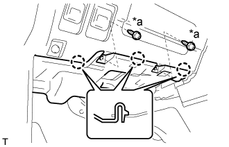
Connect the airbag connector and lock the connector lock.
Text in Illustration *a Connector Lock - NOTICE:
- When handling the airbag connector, take care not to damage the airbag wire harness.
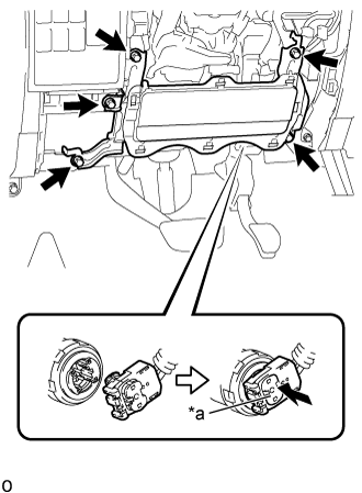 |
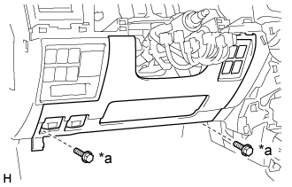
Install the driver side knee airbag assembly with the 5 bolts.
- Torque:
- 12 N*m{122 kgf*cm, 9 ft.*lbf}
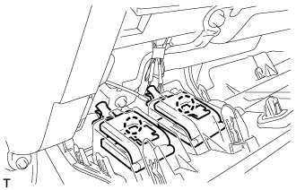
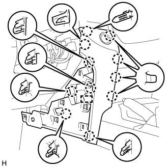
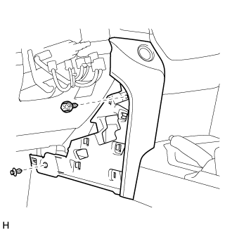
| 2. INSTALL LOWER NO. 1 INSTRUMENT PANEL FINISH PANEL |
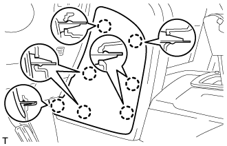
Connect the connectors.
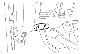
Attach the 2 claws to connect the 2 control cables.
 |
for Automatic Air Conditioning System:
Attach the 2 claws to install the room temperature sensor.

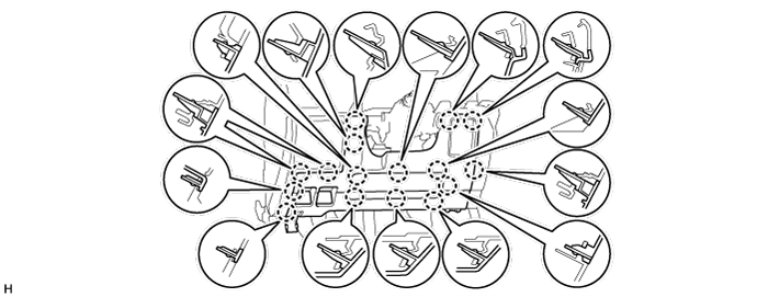
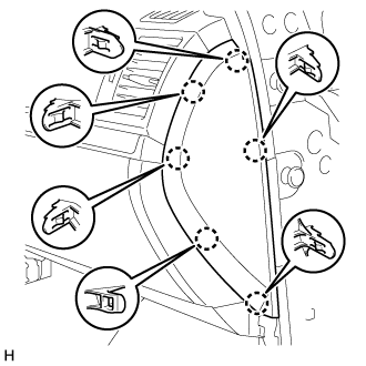
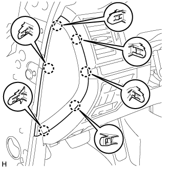
w/ Driver Side Knee Airbag:
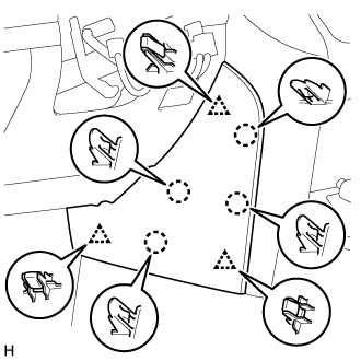
Attach the 16 claws to install the lower No. 1 instrument panel finish panel.
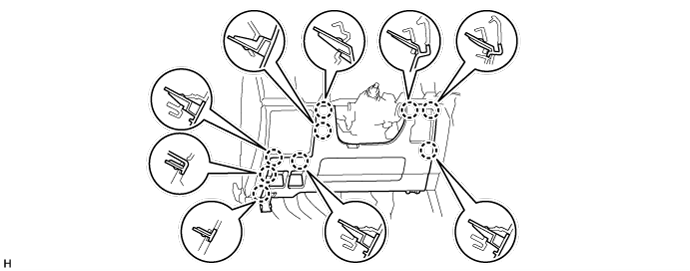
w/o Driver Side Knee Airbag:
Attach the 9 claws to install the lower No. 1 instrument panel finish panel.
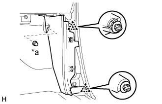
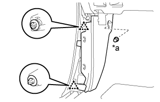
Install the 2 bolts <B>.
Text in Illustration *a Bolt <B>
 |
Attach the 2 claws to close the hole cover.
 |
| 3. INSTALL NO. 2 INSTRUMENT CLUSTER FINISH PANEL GARNISH |
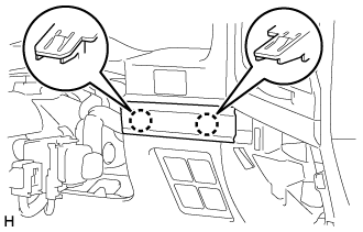 |
Attach the 2 claws to install the No. 2 instrument cluster finish panel garnish.
| 4. INSTALL NO. 1 INSTRUMENT CLUSTER FINISH PANEL GARNISH |
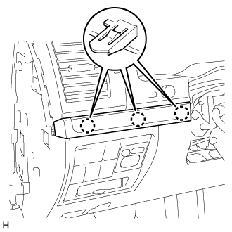 |
Attach the 3 claws to install the No. 1 instrument cluster finish panel garnish.
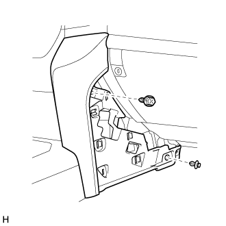
| 5. INSTALL LOWER INSTRUMENT PANEL PAD SUB-ASSEMBLY RH (for Double Swing Out Type Back Door) |
for Type A:
Attach the 11 claws and guide to install the lower instrument panel pad sub-assembly RH.
Install the screw and clip.
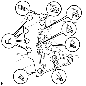
for Type B:
Attach the 7 claws to install the lower instrument panel pad sub-assembly RH.
Install the screw and clip.
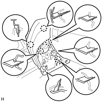
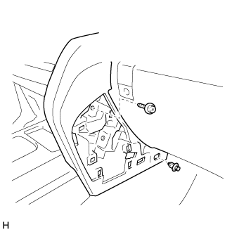
| 6. INSTALL LOWER INSTRUMENT PANEL PAD SUB-ASSEMBLY LH (except Double Swing Out Type Back Door) |
for Type A:
Connect the connectors and clamps.
Attach the 11 claws and guide to install the lower instrument panel pad sub-assembly LH.
Install the screw and clip.
for Type B:
Connect the connectors and clamps.
Attach the 8 claws and 2 guides to install the lower instrument panel pad sub-assembly LH.
Install the screw and clip.
| 7. INSTALL NO. 1 INSTRUMENT PANEL FINISH CUSHION (for Double Swing Out Type Back Door) |
for Type A:
Attach the 4 claws and 3 clips to install the No. 1 instrument panel finish panel cushion.

for Type B:
Attach the 7 claws to install the panel No. 1 instrument panel finish panel cushion.

| 8. INSTALL NO. 2 INSTRUMENT PANEL FINISH PANEL CUSHION (except Double Swing Out Type Back Door) |
for Type A:
Attach the 4 claws and 3 clips to install the No. 2 instrument panel finish panel cushion.
for Type B:
Attach the 7 claws to install the No. 2 instrument panel finish panel cushion.
| 9. INSTALL COWL SIDE TRIM BOARD RH (for Double Swing Out Type Back Door) |
 |
Attach the 2 clips to install the cowl side trim board RH.
Install the cap nut.
Text in Illustration *a Cap Nut
| 10. INSTALL COWL SIDE TRIM BOARD LH (except Double Swing Out Type Back Door) |
 |
Attach the 2 clips to install the cowl side trim board LH.
Install the cap nut.
Text in Illustration *a Cap Nut
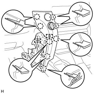
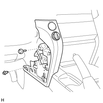
| 11. INSTALL NO. 1 INSTRUMENT PANEL UNDER COVER SUB-ASSEMBLY |
 |
Connect the connector.
Attach the 3 claws to install the No. 1 instrument panel under cover sub-assembly.
Install the 2 screws <A>.
Text in Illustration *a Screw <A>
| 12. INSTALL FRONT DOOR SCUFF PLATE RH (for Double Swing Out Type Back Door) |
- HINT:
- Use the same procedures described for the LH side.
| 13. INSTALL FRONT DOOR SCUFF PLATE LH (except Double Swing Out Type Back Door) |
 |
Attach the 7 claws and 4 clips to install the front door scuff plate LH.
| 14. INSTALL INSTRUMENT SIDE PANEL RH (for Double Swing Out Type Back Door) |
 |
w/ Airbag Cut Off Switch:
Connect the connector.
Attach the 6 claws to install the instrument side panel RH.
| 15. INSTALL INSTRUMENT SIDE PANEL LH (except Double Swing Out Type Back Door) |
 |
Attach the 6 claws to install the instrument side panel LH.
| 16. CONNECT CABLE TO NEGATIVE BATTERY TERMINAL |
- NOTICE:
- When disconnecting the cable, some systems need to be initialized after the cable is reconnected (Click here).
| 17. CHECK SRS WARNING LIGHT |
Check the SRS warning light (Click here).