Spiral Cable -- Inspection |
| 1. INSPECT SPIRAL CABLE SUB-ASSEMBLY (w/ Steering Pad Switch) |
If there are any defects as mentioned below, replace the spiral cable sub-assembly with a new one:
Scratches, cracks, dents or chips on the connector or the spiral cable sub-assembly.
Check the spiral cable sub-assembly.
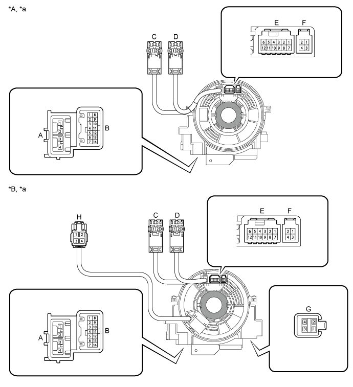
Text in Illustration *A w/ Steering Heater *B w/o Steering Heater *a Component without harness connected
(Spiral Cable sub-assembly)- - 
Interlock - - Set the spiral cable to the center position.
(Click here)Measure the resistance between each terminal of the spiral cable according to the table below.
After setting the spiral cable to the center position, rotate the spiral cable 2.5 times clockwise, and measure the resistance as shown. Then rotate the spiral cable 5 times counterclockwise, and measure the resistance as shown.
- Standard Resistance:
Tester Connection Condition Specified Condition A-1 - C-2 Always Below 1 Ω A-2 - C-1 A-3 - D-1 A-4 - D-2 B-1 - F-3 Below 3 Ω B-2 - E-7 B-2 - F-4 B-3 - E-8 B-4 - E-9 B-5 - E-10 B-6 - E-11 B-7 - E-12 B-8 - F-1 B-9 - E-1 B-9 - F-1 B-10 - E-2 B-11 - E-3 B-12 - E-4 B-13 - E-5 B-14 - E-6 G-1 - H-1 Below 3 Ω G-2 - H-3 Below 0.1 Ω G-3 - H-2 Below 3 Ω G-4 - H-4 Below 0.1 Ω
After setting the spiral cable to the center position, rotate the spiral cable 2.5 times clockwise. Then while rotating the spiral cable 5 times counterclockwise, measure the resistance as shown.
- Standard Resistance:
Tester Connection Condition Specified Condition A-1 - C-2 Always Below 1 Ω A-2 - C-1 A-3 - D-1 A-4 - D-2 B-1 - F-3 Below 3 Ω B-2 - E-7 B-2 - F-4 B-3 - E-8 B-4 - E-9 B-5 - E-10 B-6 - E-11 B-7 - E-12 B-8 - F-1 B-9 - E-1 B-9 - F-1 B-10 - E-2 B-11 - E-3 B-12 - E-4 B-13 - E-5 B-14 - E-6 G-1 - H-1 Below 3 Ω G-2 - H-3 Below 0.1 Ω G-3 - H-2 Below 3 Ω G-4 - H-4 Below 0.1 Ω
| 2. INSPECT SPIRAL CABLE SUB-ASSEMBLY (w/o Steering Pad Switch) |
If there are any defects as mentioned below, replace the spiral cable sub-assembly with a new one:
Scratches, cracks, dents or chips on the connector or the spiral cable sub-assembly.
Check the spiral cable sub-assembly.
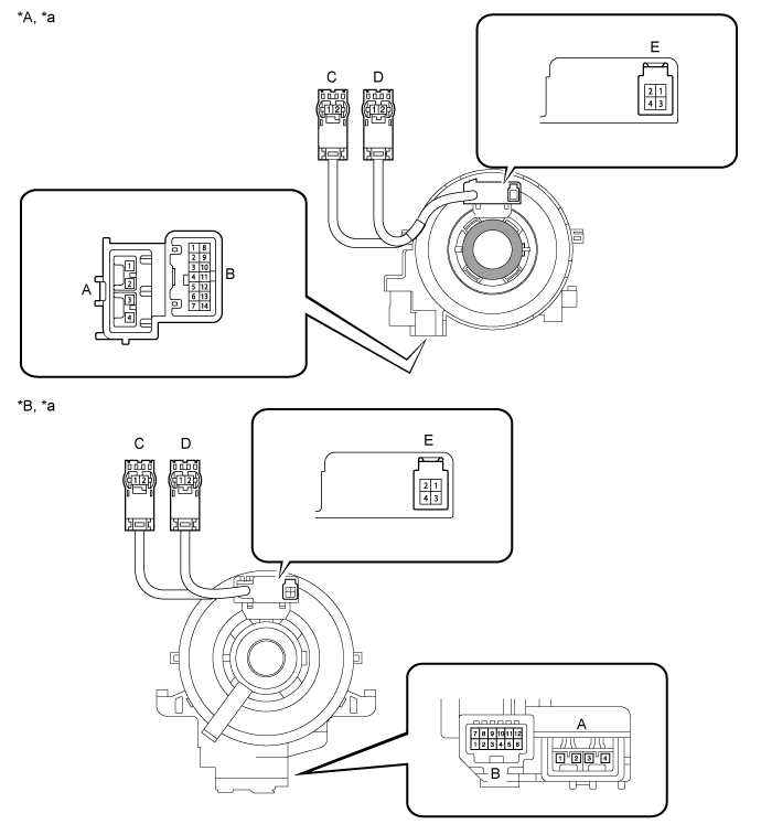
Text in Illustration *A for Type A *B for Type B *a Component without harness connected
(Spiral Cable sub-assembly)- - Interlock - - Set the spiral cable to the center position.
(Click here)Measure the resistance between each terminal of the spiral cable according to the table below.
After setting the spiral cable to the center position, rotate the spiral cable 2.5 times clockwise, and measure the resistance as shown. Then rotate the spiral cable 5 times counterclockwise, and measure the resistance as shown.
- Standard Resistance:
Tester Connection Condition Specified Condition A-1 - C-2 Always Below 1 Ω A-2 - C-1 A-3 - D-1 A-4 - D-2 B-1 - E-3 Below 3 Ω B-2 - E-4 B-9 - E-2
After setting the spiral cable to the center position, rotate the spiral cable 2.5 times clockwise. Then while rotating the spiral cable 5 times counterclockwise, measure the resistance as shown.
- Standard Resistance:
Tester Connection Condition Specified Condition A-1 - C-2 Always Below 1 Ω A-2 - C-1 A-3 - D-1 A-4 - D-2 B-1 - E-3 Below 3 Ω B-2 - E-4 B-9 - E-2