CHECK OUTER REAR VIEW MIRROR ASSEMBLY FUNCTION (MEMORY AND REACTIVATION OPERATION)
CHECK FOR DTC (ENGINE CONTROL SYSTEM)
CHECK OPERATION OF SHIFT INDICATOR
REPLACE OUTER REAR VIEW MIRROR ASSEMBLY LH
CHECK OUTER REAR VIEW MIRROR ASSEMBLY FUNCTION (REVERSE SHIFT-LINKED FUNCTION)
REPLACE OUTER REAR VIEW MIRROR ASSEMBLY RH
CHECK OUTER REAR VIEW MIRROR ASSEMBLY FUNCTION (REVERSE SHIFT-LINKED FUNCTION)
POWER MIRROR CONTROL SYSTEM (w/ Retract Mirror) - Reverse Shift-linked Function of Power Mirrors does not Operate |
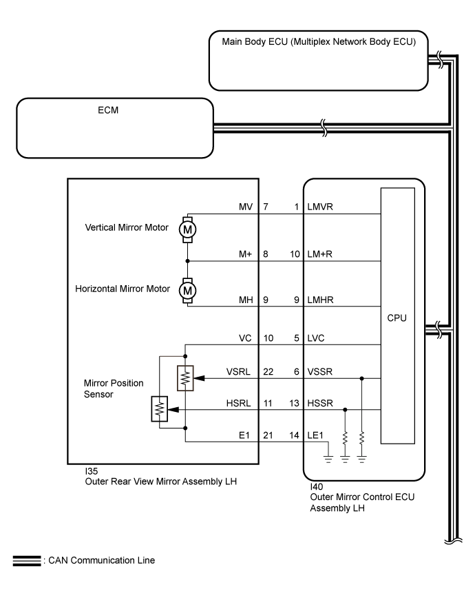
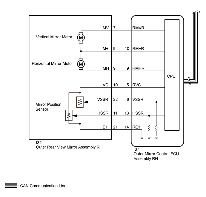
SYSTEM DESCRIPTION
ECM sends the reverse signal to the outer mirror control ECU assembly LH and RH via CAN communication. Each outer mirror control ECU assembly then performs control in response to the reverse signal.- HINT:
- The reverse shift-linked function will not occur when the mirror master switch is in the neutral position (off).
WIRING DIAGRAM
INSPECTION PROCEDURE
- NOTICE:
- First perform the communication function inspections in How to Proceed with Troubleshooting to confirm that there are no CAN communication malfunctions before troubleshooting this problem (Click here).
- If the main body ECU (multiplex network body ECU) is replaced, refer to the Entry and Start System (Click here).
| 1.CHECK OUTER REAR VIEW MIRROR ASSEMBLY FUNCTION (MEMORY AND REACTIVATION OPERATION) |
Check that the memory and reactivation function operates (Click here).
- OK:
- Memory and reactivation function operates normally.
|
| ||||
| OK | |
| 2.CHECK FOR DTC (ENGINE CONTROL SYSTEM) |
Check for DTCs.
- for 3UR-FE: Click here
- for 1UR-FE: Click here
- for 1GR-FE: Click here
- for 1VD-FTV (w/ DPF): Click here
- for 1VD-FTV (w/o DPF): Click here
- OK:
- DTCs output does not occur.
- for 3UR-FE: Click here
- HINT:
- *: Go to procedure:
- for 3UR-FE: Click here
- for 1UR-FE: Click here
- for 1GR-FE: Click here
- for 1VD-FTV (w/ DPF): Click here
- for 1VD-FTV (w/o DPF): Click here
|
| ||||
|
| ||||
| A | |
| 3.CHECK OPERATION OF SHIFT INDICATOR |
Check that the shift indicator of the combination meter operates normally.
- OK:
- Shift indicator of combination meter operates normally.
|
| ||||
| OK | |
| 4.CONFIRM MALFUNCTIONING PARTS |
Check the malfunctioning outer rear view mirror assembly (Click here).
Result Result Proceed to Both left and right outer rear view mirror assembly do not operate (for LHD) A Both left and right outer rear view mirror assembly do not operate (for RHD) B Outer rear view mirror assembly LH does not operate C Outer rear view mirror assembly RH does not operate D
|
| ||||
|
| ||||
|
| ||||
| A | ||
| ||
| 5.REPLACE OUTER REAR VIEW MIRROR ASSEMBLY LH |
Replace the outer rear view mirror assembly LH with a new or known good one (Click here).
| NEXT | |
| 6.CHECK OUTER REAR VIEW MIRROR ASSEMBLY FUNCTION (REVERSE SHIFT-LINKED FUNCTION) |
Check that the reverse shift-linked function operates (Click here).
- OK:
- Reverse shift-linked function operates normally.
|
| ||||
| OK | ||
| ||
| 7.REPLACE OUTER REAR VIEW MIRROR ASSEMBLY RH |
Replace the outer rear view mirror assembly LH with a new or known good one (Click here).
| NEXT | |
| 8.CHECK OUTER REAR VIEW MIRROR ASSEMBLY FUNCTION (REVERSE SHIFT-LINKED FUNCTION) |
Check that the reverse shift-linked function operates (Click here).
- OK:
- Reverse shift-linked function operates normally.
|
| ||||
| OK | ||
| ||