Audio And Visual System (W/ Navigation System) Vehicle Speed Signal Circuit Between Radio Receiver And Combination Meter
DESCRIPTION
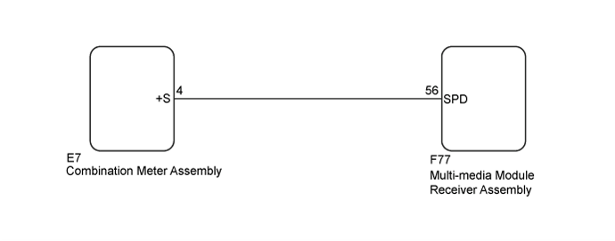
WIRING DIAGRAM
INSPECTION PROCEDURE
CHECK VEHICLE SIGNAL (OPERATION CHECK)
CHECK HARNESS AND CONNECTOR (MULTI-MEDIA MODULE RECEIVER ASSEMBLY - COMBINATION METER ASSEMBLY)
AUDIO AND VISUAL SYSTEM (w/ Navigation System) - Vehicle Speed Signal Circuit between Radio Receiver and Combination Meter |
DESCRIPTION
The multi-media module receiver assembly receives a vehicle speed signal from the combination meter assembly for DVD viewing restriction while driving, parallel parking mode of the parking assist monitor system, etc.- HINT:
- A voltage of 12 V or 5 V is output from each ECU and then input to the combination meter assembly. The signal is changed to a pulse signal at the transistor in the combination meter assembly. Each ECU controls the respective system based on the pulse signal.
- If a short occurs in any of the ECUs or in the wire harness connected to an ECU, all systems in the following diagram will not operate normally.
WIRING DIAGRAM
INSPECTION PROCEDURE
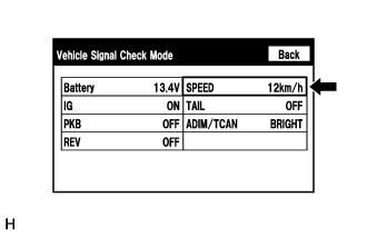
| 1.CHECK VEHICLE SIGNAL (OPERATION CHECK) |
Enter the "Vehicle Signal Check Mode" screen. Refer to Check Vehicle Signal Check Mode in Operation Check (Click here).
While driving the vehicle, compare the "SPEED" indicator to the reading on the speedometer. Check if these readings are almost equal.
- HINT:
- The combination meter assembly receives the vehicle speed signal from the skid control ECU via CAN communication. Therefore, perform the following inspection referring to values on the Data List of the skid control ECU because it is the source of the vehicle speed signal.
- OK:
- Vehicle speed displayed on the "Vehicle Signal Check Mode" screen is almost the same as the actual vehicle speed measured using the intelligent tester (Click here).
| OK |
|
|
|
| REPLACE MULTI-MEDIA MODULE RECEIVER ASSEMBLY (Click here) |
|
| 2.CHECK HARNESS AND CONNECTOR (MULTI-MEDIA MODULE RECEIVER ASSEMBLY - COMBINATION METER ASSEMBLY) |
Disconnect the F77 multi-media module receiver assembly connector.
Disconnect the E7 combination meter assembly connector.
Measure the resistance according to the value(s) in the table below.
- Standard Resistance:
Tester Connection
| Condition
| Specified Condition
|
F77-56 (SPD) - E7-4 (+S)
| Always
| Below 1 Ω
|
F77-56 (SPD) - Body ground
| Always
| 10 kΩ or higher
|
| | REPAIR OR REPLACE HARNESS OR CONNECTOR |
|
|
| OK |
|
|
|
| REPLACE MULTI-MEDIA MODULE RECEIVER ASSEMBLY (Click here) |
|