Automatic Transmission Unit -- Reassembly |
| 1. BEARING POSITION |
Check each bearing position and installation direction.

- Bearing Position:
Position Front Race Diameter
Inside/OutsideThrust Bearing Diameter
Inside/OutsideRear Race Diameter
Inside/OutsideA - 36.2 mm (1.425 in.) / 58.2 mm (2.291 in.) 44.0 mm (1.732 in.) / 62.0 mm (2.441 in.) B - 34.5 mm (1.358 in.) / 49.9 mm (1.965 in.) 36.6 mm (1.441 in.) / 51.9 mm (2.043 in.) C 46.5 mm (1.831 in.) / 60.1 mm (2.366 in.) 47.0 mm (1.850 in.) / 61.9 mm (2.437 in.) - D - 71.2 mm (2.803 in.) / 84.5 mm (3.327 in.) 71.9 mm (2.831 in.) / 87.8 mm (3.457 in.) E 30.0 mm (1.181 in.) / 49.9 mm (1.965 in.) 31.0 mm (1.221 in.) / 53.7 mm (2.112 in.) - F 31.5 mm (1.240 in.) / 57.3 mm (2.256 in.) 28.7 mm (1.130 in.) / 53.8 mm (2.118 in.) 28.7 mm (1.130 in.) / 53.5 mm (2.106 in.) G 26.2 mm (1.031 in.) / 52.7 mm (2.075 in.) 29.3 mm (1.154 in.) / 51.2 mm (2.016 in.) 29.3 mm (1.154 in.) / 54.0 mm (2.126 in.) H - 58.9 mm (2.319 in.) / 76.7 mm (3.020 in.) 62.0 mm (2.441 in.) / 82.5 mm (3.248 in.)
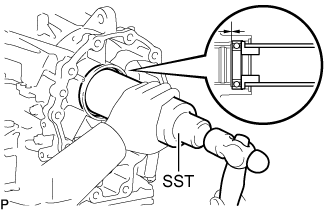
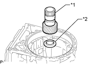
| 2. INSTALL OUTPUT SHAFT REAR RADIAL BALL BEARING |
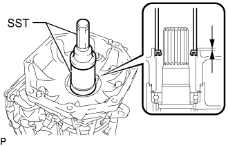
Using SST, tap in a new output shaft rear radial ball bearing to the automatic transmission case sub-assembly.
- SST
- 09316-60011(09316-00011,09316-00021)
- HINT:
- Install the output shaft rear radial ball bearing so that there is no clearance between the output shaft rear radial ball bearing and the automatic transmission case sub-assembly.
 |
Using needle-nose pliers, install the snap ring.
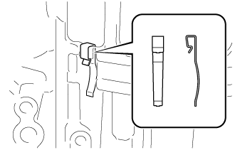
| 3. INSTALL 1ST AND REVERSE BRAKE PLATE STOPPER SPRING |
Install the 1st and reverse brake plate stopper spring to the automatic transmission case sub-assembly.
- NOTICE:
- The shapes of the parts are different. Refer to the illustration when installing the parts.
 |
| 4. INSTALL NO. 2 BRAKE PISTON |
Coat 3 new O-rings with ATF, and install them to the No. 2 brake piston.
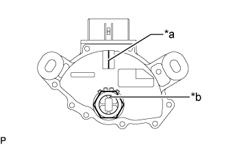
Install the No. 2 brake piston to the automatic transmission case sub-assembly.
Text in Illustration *a Spline *b Protrusion *c Spline and Protrusion - HINT:
- Make sure that the parking hole of the No. 2 brake piston is on the bottom side by engaging the 2 protrusions of the brake piston to the spline grooves of the transmission case.
 |
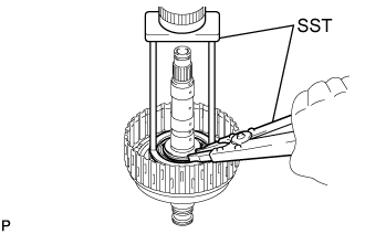
Install the No. 2 brake piston return spring sub-assembly to the automatic transmission case sub-assembly.
Set SST on the No. 2 brake piston return spring sub-assembly, tighten SST and compress the No. 2 brake piston return spring sub-assembly.
- SST
- 09380-50010(09381-05010,09381-05020,09381-05030,09381-05040,09381-05050)
Text in Illustration *1 No. 2 Brake Piston Return Spring Sub-assembly *2 Snap Ring
 |
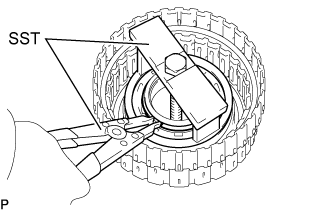
Using SST, install the snap ring.
- SST
- 09350-30020(09350-07070)
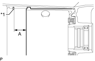
| 5. INSPECT PACK CLEARANCE OF NO. 2 BRAKE |
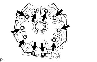
Using a vernier caliper, measure dimension A (from the tip of the No. 2 brake piston to the step in the automatic transmission case sub-assembly) in the illustration, and calculate the average.
Text in Illustration *1 Snap Ring - HINT:
- Dimension A = 35.75 to 36.25 mm (1.4075 to 1.4271 in.)
 |
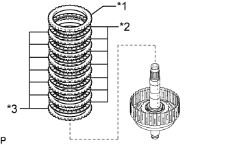
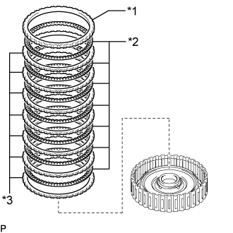
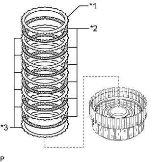
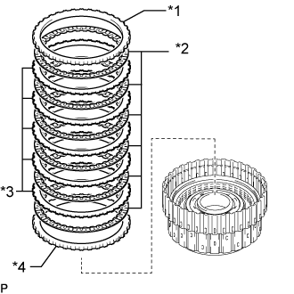
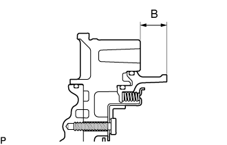
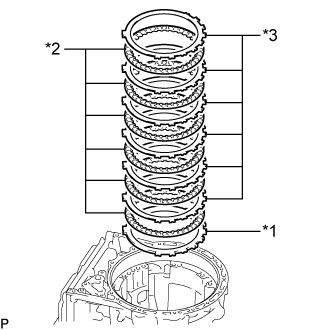
Using a vernier caliper, assemble the 6 No. 2 brakes discs, brake plate, 5 No. 2 brake plates and No. 2 brake flange as shown in the illustration. Then with a weight fixture of 500 g (17.64 oz) or less placed on the flange, measure dimension B, and calculate the average.
Text in Illustration *1 No. 2 Brake Flange *2 Brake Plate *3 No. 2 Brake Plate *4 No. 2 Brake Disc *a Weight - HINT:
- Dimension B = 33.73 to 35.07 mm (1.3280 to 1.3807 in.)
- Pack clearance = Dimension A - Dimension B
- Standard Clearance:
- 0.90 to 2.18 mm (0.0355 to 0.0858 in.)
 |
If the pack clearance is outside the standard range, select and install a No. 2 brake flange that brings the pack clearance within the standard range.
- HINT:
- There are 11 types of No. 2 brake flanges that can be used to adjust the pack clearance. Select the one with the most appropriate thickness.
- No. 2 Brake Flange Thickness:
Part No. Mark Thickness 35678-60190 
9.75 to 9.85 mm (0.3839 to 0.3877 in.) 35678-60200 
9.85 to 9.95 mm (0.3878 to 0.3917 in.) 35678-60210 
9.95 to 10.05 mm (0.3918 to 0.3956 in.) 35678-60220 
10.05 to 10.15 mm (0.3957 to 0.3996 in.) 35678-60230 
10.15 to 10.25 mm (0.3997 to 0.4035 in.) 35678-60240 
10.25 to 10.35 mm (0.4036 to 0.4074 in.) 35678-60250 
10.35 to 10.45 mm (0.4075 to 0.4114 in.) 35678-60260 
10.45 to 10.55 mm (0.4115 to 0.4153 in.) 35678-60270 
10.55 to 10.65 mm (0.4154 to 0.4192 in.) 35678-60280 
10.65 to 10.75 mm (0.4193 to 0.4232 in.) 35678-60290 
10.75 to 10.85 mm (0.4233 to 0.4271 in.)
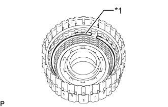
| 6. INSTALL DIRECT CLUTCH PISTON |
Coat a new O-ring with ATF, and install it to the direct clutch drum sub-assembly.
Coat a new O-ring with ATF, and install it to the direct clutch piston.
Install the direct clutch piston to the direct clutch drum sub-assembly.
Text in Illustration *1 Direct Clutch Piston
 |
Coat a new O-ring with ATF, and install it to the No. 2 clutch balancer.
Install the direct clutch return spring sub-assembly and No. 2 clutch balancer to the direct clutch drum sub-assembly.
Text in Illustration *1 No. 2 Clutch Balancer *2 Direct Clutch Return Spring Sub-assembly
 |
Place SST on the No. 2 clutch balancer and compress the direct clutch return spring sub-assembly with a press.
- SST
- 09387-00020
 |
Using SST, install the snap ring.
- SST
- 09350-30020(09350-07070)
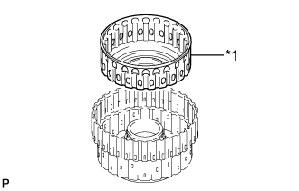
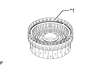
| 7. INSTALL NO. 2 CLUTCH DISC SET |
Install the 7 No. 2 clutch plates, 7 No. 2 clutch discs and the No. 2 clutch flange to the direct clutch drum sub-assembly.
- Install in order:
- *3 - *2 - *3 - *2 - *3 - *2 - *3 - *2 - *3 - *2 - *3 - *2 - *3 - *2 - *1
Text in Illustration *1 No. 2 Clutch Flange *2 No. 2 Clutch Disc *3 No. 2 Clutch Plate - NOTICE:
- Make sure that the No. 2 clutch discs, No. 2 clutch plates and the No. 2 clutch flange are installed in the correct order.
 |
Using a screwdriver, install the snap ring to the direct clutch drum sub-assembly.
Text in Illustration *1 Oil Seal Ring *a Protective Tape - NOTICE:
- Be careful not to damage the direct clutch drum sub-assembly.
- HINT:
- Tape the screwdriver tip before use.
 |
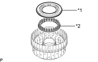
Coat a new oil seal ring with ATF, and install them to the direct multiple disc clutch assembly.
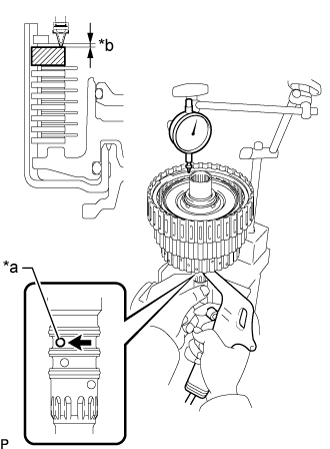
| 8. INSPECT PACK CLEARANCE OF NO. 2 CLUTCH |
Using a dial indicator, measure the moving distance (distance A) of the No. 2 clutch flange at both ends across the diameter while blowing compressed air (196 kPa, 2.0 kgf/cm2, 28 psi) from the oil hole as shown in the illustration, and calculate the average.
- Standard Clearance:
- 1.05 to 1.25 mm (0.0414 to 0.0492 in.)
Text in Illustration *a Oil Hole *b Distance A
 |
If the pack clearance is outside the standard range, select and install a No. 2 clutch flange that brings the pack clearance within the standard range.
- HINT:
- There are 9 types of No. 2 clutch flanges that can be used to adjust the pack clearance. Select the one with the most appropriate thickness.
- No. 2 Clutch Flange Thickness:
Part No. Mark Thickness 35635-50181 40 3.95 to 4.05 mm (0.1556 to 0.1594 in.) 35635-50231 41 4.05 to 4.15 mm (0.1595 to 0.1633 in.) 35635-50191 42 4.15 to 4.25 mm (0.1634 to 0.1673 in.) 35635-50241 43 4.25 to 4.35 mm (0.1674 to 0.1712 in.) 35635-50201 44 4.35 to 4.45 mm (0.1713 to 0.1751 in.) 35635-50251 45 4.45 to 4.55 mm (0.1752 to 0.1791 in.) 35635-50211 46 4.55 to 4.65 mm (0.1792 to 0.1830 in.) 35635-50261 47 4.65 to 4.75 mm (0.1831 to 0.1870 in.) 35635-50221 48 4.75 to 4.85 mm (0.1871 to 0.1909 in.)
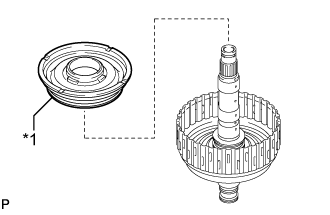
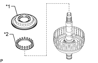
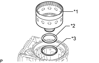
| 9. INSTALL DIRECT MULTIPLE DISC CLUTCH ASSEMBLY |
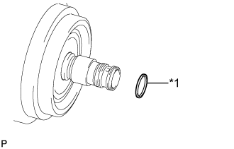
Coat a new oil seal ring with ATF, and install them to the direct multiple disc clutch assembly.
Text in Illustration *1 Oil Seal Ring - NOTICE:
- Do not expand the gap of the oil seal rings excessively.
 |
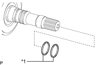
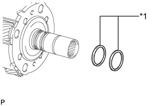
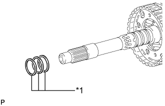
Coat 2 new oil seal ring with ATF, and install them to the output shaft sub-assembly.
Text in Illustration *1 Oil Seal Ring - NOTICE:
- Do not expand the gap of the oil seal rings excessively.
 |
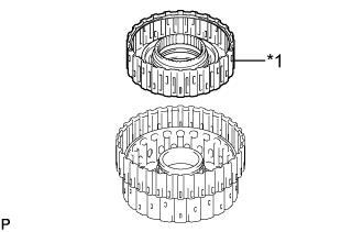
Install the thrust needle roller bearing and 2 thrust bearing races to the direct multiple disc clutch assembly.
- Thrust Needle Roller Bearing and Thrust Bearing Race Diameter:
Item Inside Outside for Front Side:
Thrust bearing race (G)26.2 mm (1.031 in.) 52.7 mm (2.075 in.) Thrust needle roller bearing (G) 29.3 mm (1.154 in.) 51.2 mm (2.016 in.) for Rear Side:
Thrust bearing race (G)29.3 mm (1.154 in.) 54.0 mm (2.126 in.)
Text in Illustration *1 Direct Multiple Disc Clutch Assembly *2 Thrust Needle Roller Bearing (G) *3 Thrust Bearing Race (G) *4 Output Shaft Sub-assembly - NOTICE:
- Use a small amount of MP grease to make the thrust needle roller bearing and thrust bearing race stay securely in place.
 |
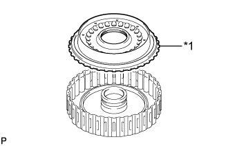
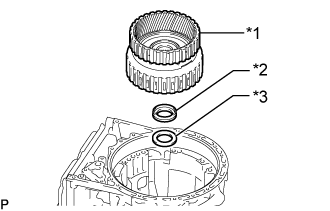
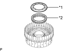
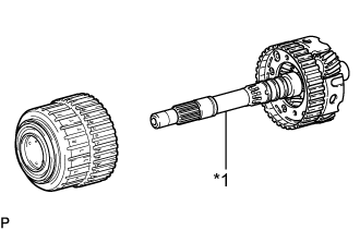
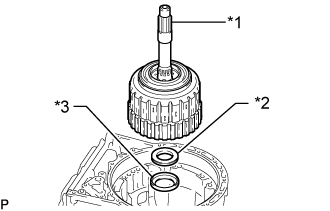
Install the direct multiple disc clutch assembly to the output shaft sub-assembly.
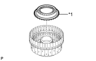
| 10. INSTALL REAR PLANETARY RING GEAR |
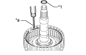
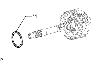
Install the snap ring to the groove of the output shaft sub-assembly.
Text in Illustration *1 Rear Planetary Ring Gear *2 Snap Ring *3 Output Shaft Sub-assembly
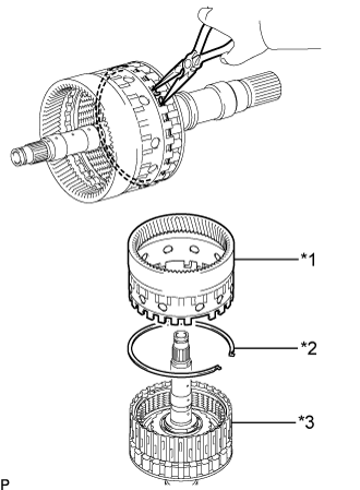 |
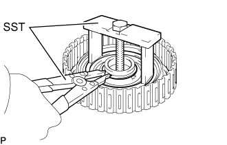
Using needle-nose pliers, attach the snap ring to install the rear planetary ring gear to the output shaft sub-assembly.
| 11. INSTALL DIRECT MULTIPLE DISC CLUTCH ASSEMBLY WITH REAR PLANETARY RING GEAR AND OUTPUT SHAFT SUB-ASSEMBLY |
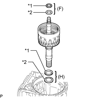
Install the 2 thrust needle bearings, 2 thrust bearing races, direct multiple disc clutch assembly with rear planetary ring gear and output shaft sub-assembly to the automatic transmission case sub-assembly.
- Thrust Needle Roller Bearing and Thrust Bearing Race Diameter:
Item Inside Outside Thrust bearing race (H) 62.0 mm (2.441 in.) 82.5 mm (3.248 in.) Thrust needle roller bearing (H) 58.9 mm (2.319 in.) 76.7 mm (3.020 in.) for Rear Side:
Thrust bearing race (F)28.7 mm (1.130 in.) 53.5 mm (2.106 in.) Thrust needle roller bearing (F) 28.7 mm (1.130 in.) 53.8 mm (2.118 in.)
Text in Illustration *1 Thrust Needle Roller Bearing *2 Thrust Bearing Race - NOTICE:
- Use a small amount of MP grease to make the thrust needle roller bearing and thrust bearing race stay securely in place.
 |
| 12. INSTALL REAR PLANETARY GEAR ASSEMBLY |
Install the thrust bearing race, rear planetary gear assembly and thrust needle roller bearing to the automatic transmission case sub-assembly.
- Thrust Needle Roller Bearing and Thrust Bearing Race Diameter:
Item Inside Outside for Front Side
Thrust bearing race (F)31.5 mm (1.240 in.) 57.3 mm (2.256 in.) Thrust needle roller bearing (E) 31.0 mm (1.221 in.) 53.7 mm (2.114 in.)
Text in Illustration *1 Thrust Needle Roller Bearing *2 Rear Planetary Gear Assembly *3 Thrust Bearing Race - NOTICE:
- Before installing the rear planetary gear assembly, apply ATF to the sliding surfaces of the rear planetary gear assembly bush. After the installation, check that the rear planetary gear assembly rotates smoothly.
- Use a small amount of MP grease to make the thrust needle roller bearing and thrust bearing race stay securely in place.
 |
| 13. INSTALL REAR PLANETARY SUN GEAR SUB-ASSEMBLY |
Install the thrust bearing race and rear planetary sun gear sub-assembly to the automatic transmission case sub-assembly.
- Standard Thrust Bearing Race Diameter:
Item Inside Outside Thrust bearing race (E) 30.0 mm (1.181 in.) 49.9 mm (1.965 in.)
Text in Illustration *1 Rear Planetary Sun Gear Sub-assembly *2 Thrust Bearing Race (E) - NOTICE:
- Before installing the rear planetary sun gear sub-assembly, apply ATF to the sliding surfaces of the rear planetary sun gear sub-assembly bush. After the installation, check that the rear planetary sun gear sub-assembly rotates smoothly.
- Use a small amount of MP grease to make the thrust bearing race stay securely in place.
 |
| 14. INSTALL NO. 2 BRAKE DISC SET |
Install the No. 2 brake flange, 6 No. 2 brake discs, 5 No. 2 brake plates and brake plate to the automatic transmission case sub-assembly.
- Install in order:
- *4 - *2 - *3 - *2 - *3 - *2 - *3 - *2 - *3 - *2 - *3 - *2 - *1
Text in Illustration *1 Brake Plate *2 No. 2 Brake Disc *3 No. 2 Brake Plate *4 No. 2 Brake Flange - NOTICE:
- Make sure that the No. 2 brake discs, No. 2 brake plates, brake plate and No. 2 brake flange are installed in the correct order.
- HINT:
- Assemble the automatic transmission case sub-assembly, No. 2 brake flange, No. 2 brake plate and brake plate by aligning their grooves as shown in the illustration.
Text in Illustration *1 Brake Plate, No. 2 Brake Plate and No. 2 Brake Flange - - *a Groove - -
 |
Install the snap ring to the automatic transmission case sub-assembly.
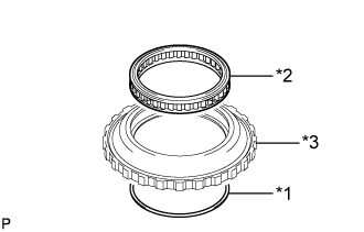
| 15. INSTALL NO. 1 ONE-WAY CLUTCH |
Install the No. 1 one-way clutch to the one-way clutch outer race with the snap ring.
Text in Illustration *1 Snap Ring *2 No. 1 One-way Clutch *3 One-way Clutch Outer Race - NOTICE:
- Make sure that the No. 1 one-way clutch is oriented correctly.
 |
| 16. INSPECT NO. 1 ONE-WAY CLUTCH |
Install the No. 1 one-way clutch to the rear planetary gear assembly.
Hold the rear planetary gear assembly and turn the No. 1 one-way clutch.
Text in Illustration 
Lock 
Free
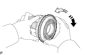 |
Check that the No. 1 one-way clutch turns freely counterclockwise and locks clockwise.
If the No. 1 one-way clutch does not operate normally, replace it.
| 17. INSTALL ONE-WAY CLUTCH OUTER RACE WITH NO. 1 ONE-WAY CLUTCH |
Install the one-way clutch outer race with No. 1 one-way clutch to the automatic transmission case sub-assembly.
 |
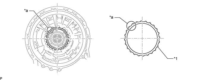
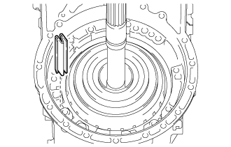
Using SST, install the snap ring to the automatic transmission case sub-assembly.
- SST
- 09350-30020(09350-07060)
- NOTICE:

- Install the snap ring so that its end gap will be within the range shown in the illustration.
 |
| 18. INSTALL SUN GEAR INPUT DRUM SUB-ASSEMBLY |
Install the thrust bearing race, thrust needle roller bearing and sun gear input drum sub-assembly to the automatic transmission case sub-assembly.
- Thrust Needle Roller Bearing and Thrust Bearing Race Diameter:
Item Inside Outside Thrust bearing race (D) 71.9 mm (2.831 in.) 87.8 mm (3.457 in.) Thrust needle roller bearing (D) 71.2 mm (2.803 in.) 84.5 mm (3.327 in.)
Text in Illustration *1 Sun Gear Input Drum Sub-assembly *2 Thrust Needle Roller Bearing (D) *3 Thrust Bearing Race (D) - NOTICE:
- Before installing the sun gear input drum sub-assembly, apply ATF to the sliding surfaces of the sun gear input drum sub-assembly bush. After the installation, check that the sun gear input drum sub-assembly rotates smoothly.
- Use a small amount of MP grease to make the thrust needle roller bearing and thrust bearing race stay securely in place.
 |
| 19. INSTALL FORWARD CLUTCH PISTON |
Coat 2 new O-rings with ATF, and install them to the forward clutch piston.
Install the forward clutch piston to the forward clutch drum sub-assembly.
Text in Illustration *1 Forward Clutch Piston
 |
Coat a new O-ring with ATF, and install it to the No. 1 clutch balancer.
Install the forward clutch return spring sub-assembly and No. 1 clutch balancer to the forward clutch drum sub-assembly.
Text in Illustration *1 No. 1 Clutch Balancer *2 Forward Clutch Return Spring Sub-assembly
 |
Set SST on the No. 1 clutch balancer, tighten SST and compress the No. 1 clutch balancer.
- SST
- 09380-50010(09381-05010,09381-05020,09381-05030,09381-05040,09381-05050)
- NOTICE:
- Stop pressing when the balancer is lowered to the place 1 to 2 mm (0.039 to 0.078 in.) from the snap ring groove to prevent spring sheet deformation.
 |
Using SST, install the snap ring.
- SST
- 09350-30020(09350-07070)
- NOTICE:
- Be sure that the end gap of the snap ring is not aligned with the spring retainer claw.
- Do not expand the snap ring excessively.
| 20. INSTALL FORWARD MULTIPLE CLUTCH DISC SET |
Install the 7 forward multiple clutch plates, 7 forward multiple clutch discs and forward clutch flange to the forward clutch drum sub-assembly.
- Install in order:
- *3 - *2 - *3 - *2 - *3 - *2 - *3 - *2 - *3 - *2 - *3 - *2 - *3 - *2 - *1
Text in Illustration *1 Forward Clutch Flange *2 Forward Multiple Clutch Disc *3 Forward Multiple Clutch Plate - NOTICE:
- Make sure that the forward multiple clutch discs, forward multiple clutch plates and the forward clutch flange are installed in the correct order.
 |
Install the snap ring to the forward clutch drum sub-assembly.
Text in Illustration *1 Snap Ring
 |
| 21. INSPECT PACK CLEARANCE OF FORWARD MULTIPLE CLUTCH |
Temporarily assemble the front planetary gear assembly to the forward clutch drum sub-assembly.
Using a dial indicator, measure the moving distance (distance A) of the forward clutch flange at both ends across the diameter while blowing compressed air (196 kPa, 2.0 kgf/cm2, 28 psi) from the oil hole as shown in the illustration, and calculate the average.
Text in Illustration *a Oil Hole *b Distance A - Standard Clearance:
- 1.05 to 1.25 mm (0.0414 to 0.0492 in.)
 |
If the pack clearance is outside the standard range, select and install a forward clutch flange that brings the pack clearance within the standard range.
- HINT:
- There are 9 types of forward clutch flanges that can be used to adjust the pack clearance. Select the one with the most appropriate thickness.
- Forward Clutch Flange Thickness:
Part No. Mark Thickness 35635-50090 0 4.35 to 4.45 mm (0.1713 to 0.1751 in.) 35635-50100 1 4.45 to 4.55 mm (0.1752 to 0.1791 in.) 35635-50110 2 4.55 to 4.65 mm (0.1792 to 0.1830 in.) 35635-50120 3 4.65 to 4.75 mm (0.1831 to 0.1870 in.) 35635-50130 4 4.75 to 4.85 mm (0.1871 to 0.1909 in.) 35635-50140 5 4.85 to 4.95 mm (0.1910 to 0.1948 in.) 35635-50150 6 4.95 to 5.05 mm (0.1949 to 0.1988 in.) 35635-50160 7 5.05 to 5.15 mm (0.1989 to 0.2027 in.) 35635-50170 8 5.15 to 5.25 mm (0.2028 to 0.2066 in.)
| 22. INSTALL FRONT PLANETARY RING GEAR |
Using needle-nose pliers, install the snap ring to the groove of forward multiple disc clutch assembly.
Text in Illustration *1 Front Planetary Ring Gear *2 Snap Ring *3 Forward Multiple Disc Clutch Assembly
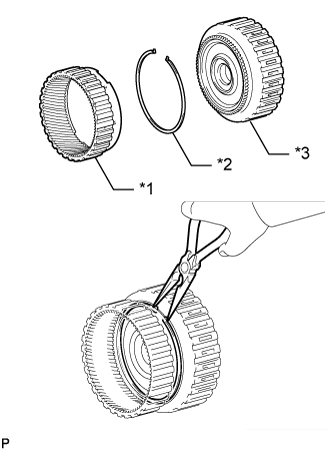 |
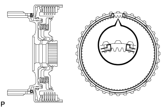
Using needle-nose pliers, contract the snap ring and install the front planetary ring gear to the forward multiple disc clutch assembly.
- NOTICE:
- Confirm that the snap ring is correctly located in the groove of the forward multiple disc clutch assembly as shown in the illustration.
 |
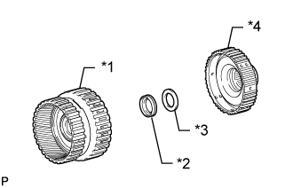
| 23. INSTALL FORWARD MULTIPLE DISC CLUTCH HUB |
Install the thrust needle roller bearing, thrust bearing race and forward multiple disc clutch assembly with front planetary ring gear to the forward multiple disc clutch hub.
- Thrust Needle Roller Bearing and Thrust Bearing Race Diameter:
Item Inside Outside Thrust needle roller bearing (B) 34.5 mm (1.358 in.) 49.9 mm (1.965 in.) Thrust bearing race (B) 36.6 mm (1.441 in.) 51.9 mm (2.043 in.)
Text in Illustration *1 Forward Multiple Disc Clutch Assembly with Front Planetary Ring Gear *2 Thrust Needle Roller Bearing (B) *3 Thrust Bearing Race (B) *4 Forward Multiple Disc Clutch Hub - NOTICE:
- Use a small amount of MP grease to make the thrust needle roller bearing and thrust bearing race stay securely in place.
 |
| 24. INSTALL FORWARD MULTIPLE DISC CLUTCH ASSEMBLY WITH FRONT PLANETARY RING GEAR AND FORWARD MULTIPLE DISC CLUTCH HUB |
Install the thrust bearing race, thrust needle roller bearing and forward multiple disc clutch assembly with front planetary ring gear and forward multiple disc clutch hub to the automatic transmission case sub-assembly.
- Thrust Needle Roller Bearing and Thrust Bearing Race Diameter:
Item Inside Outside Thrust needle race (C) 47.0 mm (1.850 in.) 61.9 mm (2.437 in.) Thrust bearing roller bearing (C) 46.5 mm (1.831 in.) 60.1 mm (2.366 in.)
Text in Illustration *1 Forward Multiple Disc Clutch Assembly with Front Planetary Ring Gear *2 Thrust Bearing Race (C) *3 Thrust Needle Roller Bearing (C) - NOTICE:
- Before installing the forward multiple disc clutch assembly, apply ATF to the sliding surfaces of the forward multiple disc clutch assembly bush. After the installation, check that the forward multiple disc clutch assembly rotates smoothly.
- Use a small amount of MP grease to make the thrust needle roller bearing and thrust needle roller bearing race stay securely in place.
 |
| 25. INSTALL REVERSE CLUTCH PISTON SUB-ASSEMBLY |
Coat a new O-ring with ATF, and install it to the reverse clutch drum sub-assembly.
Install the reverse clutch piston sub-assembly to the reverse clutch drum sub-assembly.
Text in Illustration *1 Reverse Clutch Piston Sub-assembly
 |
Coat a new O-ring with ATF, and install it to the No. 3 clutch balancer.
Install the reverse clutch return spring sub-assembly (front) and No. 3 clutch balancer to the reverse clutch drum sub-assembly.
Text in Illustration *1 No. 3 Clutch Balancer *2 Reverse Clutch Return Spring Sub-assembly (Front)
 |
Set SST on the No. 3 clutch balancer, tighten SST and compress the No. 3 clutch balancer.
- SST
- 09380-50010(09381-05010,09381-05020,09381-05030,09381-05040,09381-05050)
- NOTICE:
- Stop pressing when the balancer is lowered to the place 1.0 to 2.0 mm (0.0394 to 0.0787 in.) from the snap ring groove to prevent spring sheet deformation.
 |
Using SST, install the snap ring.
- SST
- 09350-30020(09350-07070)
- NOTICE:
- Be sure that the end gap of the snap ring is not aligned with the spring retainer claw.
- Do not expand the snap ring excessively.
| 26. INSTALL OVERDRIVE DIRECT CLUTCH DRUM SUB-ASSEMBLY |
Coat 3 new O-rings with ATF, and install them to the overdrive direct clutch drum sub-assembly.
Install the overdrive direct clutch drum sub-assembly to the reverse clutch drum sub-assembly.
Text in Illustration *1 Overdrive Direct Clutch Drum Sub-assembly
 |
| 27. INSTALL NO. 4 CLUTCH PISTON |
Coat a new O-ring with ATF, and install it to the No. 4 clutch piston.
Install the No. 4 clutch piston to the overdrive direct clutch drum sub-assembly.
Text in Illustration *1 No. 4 Clutch Piston
 |
Install the reverse clutch return spring sub-assembly (rear) and reverse clutch balancer to the overdrive direct clutch drum sub-assembly.
Text in Illustration *1 Reverse Clutch Balancer *2 Reverse Clutch Return Spring Sub-assembly (Rear)
 |
Set SST on the reverse clutch balancer, tighten SST and compress the reverse clutch balancer.
- SST
- 09380-50010(09381-05010,09381-05020,09381-05030,09381-05040,09381-05050)
- NOTICE:
- Stop pressing when the balancer is lowered to the place 1.0 to 2.0 mm (0.0394 to 0.0787 in.) from the snap ring groove to prevent spring sheet deformation.
 |
Using SST, install the snap ring.
- SST
- 09350-30020(09350-07070)
- NOTICE:
- Be sure that the end gap of the snap ring is not aligned with the spring retainer claw.
- Do not expand the snap ring excessively.
| 28. INSTALL OVERDRIVE DIRECT CLUTCH DISC |
Install the 6 overdrive direct clutch plates, 6 overdrive direct clutch discs and overdrive clutch flange to the overdrive direct clutch drum sub-assembly.
- Install in order:
- *3 - *2 - *3 - *2 - *3 - *2 - *3 - *2 - *3 - *2 - *3 - *2 - *1
Text in Illustration *1 Overdrive Clutch Flange *2 Overdrive Direct Clutch Disc *3 Overdrive Direct Clutch Plate - NOTICE:
- Make sure that the overdrive direct clutch discs, overdrive direct clutch plates and the overdrive clutch flange are installed in the correct order.
 |
Install the snap ring to the overdrive direct clutch drum sub-assembly.
Text in Illustration *1 Snap Ring
 |
| 29. INSPECT PACK CLEARANCE OF OVERDRIVE DIRECT CLUTCH |
Using a dial indicator, measure the moving distance (distance A) of the reverse clutch flange at both ends across the diameter while blowing compressed air (300 kPa, 3.1 kgf/cm2, 44 psi) from the oil hole as shown in the illustration, and calculate the average.

Text in Illustration *a Oil Hole *b Distance A *c Speed Sensor Hole - - - Standard Clearance:
- 1.19 to 1.39 mm (0.0469 to 0.0547 in.)
If the pack clearance is outside the standard range, select and install a overdrive clutch flange that brings the pack clearance within the standard range.
- HINT:
- There are 11 types of overdrive clutch flanges that can be used to adjust the pack clearance. Select the one with the most appropriate thickness.
- Overdrive Clutch Flange Thickness:
Part No. Thickness 34615-60010 2.85 to 2.95 mm (0.1123 to 0.1161 in.) 34615-60020 2.95 to 3.05 mm (0.1162 to 0.1200 in.) 34615-60030 3.05 to 3.15 mm (0.1201 to 0.1240 in.) 34615-60040 3.15 to 3.25 mm (0.1241 to 0.1279 in.) 34615-60050 3.25 to 3.35 mm (0.1280 to 0.1318 in.) 34615-60060 3.35 to 3.45 mm (0.1319 to 0.1358 in.) 34615-60070 3.45 to 3.55 mm (0.1359 to 0.1397 in.) 34615-60080 3.55 to 3.65 mm (0.1398 to 0.1437 in.) 34615-60090 3.65 to 3.75 mm (0.1438 to 0.1476 in.) 34615-60100 3.75 to 3.85 mm (0.1477 to 0.1515 in.) 34615-60110 3.85 to 3.95 mm (0.1516 to 0.1555 in.)
| 30. INSTALL NO. 3 CLUTCH DISC SET |
Install the 6 No. 3 clutch plates, 6 No. 3 clutch discs and No. 3 clutch flange to the reverse clutch drum sub-assembly.
- Install in order:
- *4 - *2 - *3 - *2 - *3 - *2 - *3 - *2 - *3 - *2 - *3 - *2 - *1
- No. 3 Clutch Plate Thickness:
Item Thickness No. 3 Clutch Plate (A) 1.8 mm (0.0709 in.) No. 3 Clutch Plate (B) 3.5 mm (0.138 in.)
Text in Illustration *1 No. 3 Clutch Flange *2 No. 3 Clutch Discs *3 No. 3 Clutch Plate (A) *4 No. 3 Clutch Plate (B) - NOTICE:
- Make sure that the No. 3 clutch discs, No. 3 clutch plates and the No. 3 clutch flange are installed in the correct order.
 |
Install the snap ring to the reverse clutch drum sub-assembly.
Text in Illustration *1 Snap Ring
 |
| 31. INSPECT PACK CLEARANCE OF NO. 3 CLUTCH |
Using a dial indicator, measure the moving distance (distance A) of the No. 3 clutch flange at both ends across the diameter while blowing compressed air (196 kPa, 2.0 kgf/cm2, 28 psi) from the oil hole as shown in the illustration, and calculate the average.

Text in Illustration *a Oil Hole *b Distance A *c Speed Sensor Hole - - - Standard Clearance:
- 0.90 to 1.10 mm (0.0355 to 0.0433 in.)
If the pack clearance is outside the standard range, select and install a No. 3 clutch flange that brings the pack clearance within the standard range.
- HINT:
- There are 11 types of No. 3 clutch flanges that can be used to adjust the pack clearance. Select the one with the most appropriate thickness.
- No. 3 Clutch Flange Thickness:
Part No. Thickness 34649-60250 3.75 to 3.85 mm (0.1477 to 0.1515 in.) 34649-60260 3.85 to 3.95 mm (0.1516 to 0.1555 in.) 34649-60270 3.95 to 4.05 mm (0.1556 to 0.1594 in.) 34649-60280 4.05 to 4.15 mm (0.1595 to 0.1633 in.) 34649-60290 4.15 to 4.25 mm (0.1634 to 0.1673 in.) 34649-60300 4.25 to 4.35 mm (0.1674 to 0.1712 in.) 34649-60310 4.35 to 4.45 mm (0.1713 to 0.1751 in.) 34649-60320 4.45 to 4.55 mm (0.1752 to 0.1791 in.) 34649-60330 4.55 to 4.65 mm (0.1792 to 0.1830 in.) 34649-60340 4.65 to 4.75 mm (0.1831 to 0.1870 in.) 34649-60350 4.75 to 4.85 mm (0.1871 to 0.1909 in.)
| 32. INSTALL FRONT PLANETARY GEAR ASSEMBLY |
Install the front planetary gear radial needle roller bearing to the front planetary gear assembly.
Text in Illustration *1 Front Planetary Gear Radial Needle Roller Bearing - NOTICE:
- Do not expand the front planetary gear radial needle roller bearing excessively.
 |
Coat 2 new oil seal rings with ATF, and install them to the front planetary gear assembly.
Text in Illustration *1 Oil Seal Ring - NOTICE:
- Do not expand the oil seal ring ends excessively.
 |
Coat 3 new oil seal rings with ATF, and install them to the front planetary gear assembly.
Text in Illustration *1 Oil Seal Ring - NOTICE:
- Do not expand the oil seal ring ends excessively.
 |
Install the planetary carrier thrust washer to the front planetary gear assembly.
Text in Illustration *1 Planetary Carrier Thrust Washer - NOTICE:
- Use a small amount of MP grease to make the planetary carrier thrust washer stay securely in place.
 |
Install the front planetary sun gear to the front planetary gear assembly.
Text in Illustration *1 Front Planetary Sun Gear
 |
Assemble the front planetary gear assembly together with the front planetary sun gear to the overdrive and reverse multiple disc clutch assembly.
Text in Illustration *1 Front Planetary Gear Assembly
 |
| 33. INSPECT PACK CLEARANCE OF NO. 1 BRAKE |
Using a vernier caliper, measure dimension A (from the step of the oil pump assembly installation surface of the automatic transmission case sub-assembly to the step of the No. 1 brake flange installation surface) in the illustration, and calculate the average.
Text in Illustration *1 Snap Ring - HINT:
- Dimension A = 46.18 to 46.54 mm (1.8182 to 1.8322 in.)
 |
Using a vernier caliper, measure dimension B (from the flange face of the oil pump assembly to the tip of the No. 1 brake piston) in the illustration, and calculate the average.
- HINT:
- Dimension B = 19.23 to 19.57 mm (0.7571 to 0.7704 in.)
 |
Using a vernier caliper, assemble the 6 No. 1 brake plates, 6 No. 1 brake discs and No. 1 brake flange, measure dimension C in the illustration and calculate the average.
Text in Illustration *1 No. 1 Brake Flange *2 No. 1 Brake Disc *3 No. 1 Brake Plate - HINT:
- Dimension C = 25.15 to 26.45 mm (0.9902 to 1.0413 in.)
- Pack clearance = Dimension A - Dimension B - Dimension C
- Standard Clearance:
- 0.90 to 1.10 mm (0.0355 to 0.0433 in.)
 |
If the pack clearance is outside the standard range, select and install a No. 1 brake flange that brings the pack clearance within the standard range.
- HINT:
- There are 7 types of No. 1 brake flanges that can be used to adjust the pack clearance. Select the one with the most appropriate thickness.
- No. 1 Brake Flange Thickness:
Part No. Mark Thickness 35676-60190 0 4.45 to 4.55 mm (0.1752 to 0.1791 in.) 35676-60200 1 4.55 to 4.65 mm (0.1792 to 0.1830 in.) 35676-60210 2 4.65 to 4.75 mm (0.1831 to 0.1870 in.) 35676-60220 3 4.75 to 4.85 mm (0.1871 to 0.1909 in.) 35676-60230 4 4.85 to 4.95 mm (0.1910 to 0.1948 in.) 35676-60240 5 4.95 to 5.05 mm (0.1949 to 0.1988 in.) 35676-60250 6 5.05 to 5.15 mm (0.1989 to 0.2027 in.)
| 34. INSTALL OVERDRIVE AND REVERSE MULTIPLE DISC CLUTCH ASSEMBLY AND FRONT PLANETARY GEAR ASSEMBLY |
Install the thrust bearing race, thrust needle roller bearing, and overdrive and reverse multiple disc clutch assembly and front planetary gear assembly to the automatic transmission case sub-assembly.
- Thrust Needle Roller Bearing and Thrust Bearing Race Diameter:
Item Inside Outside Thrust needle roller bearing (A) 36.2 mm (1.425 in.) 58.2 mm (2.291 in.) Thrust bearing race (A) 44.0 mm (1.732 in.) 62.0 mm (2.441 in.)
Text in Illustration *1 Overdrive and Reverse Multiple Disc Clutch Assembly and Front Planetary Gear Assembly *2 Thrust Needle Roller Bearing (A) *3 Thrust Bearing Race (A) - NOTICE:
- Before installing the reverse clutch drum sub-assembly, apply ATF to the sliding surfaces of the reverse clutch drum sub-assembly. After the installation, check that the overdrive direct clutch drum sub-assembly rotates smoothly.
- Use a small amount of MP grease to make the thrust bearing and thrust bearing race stay securely in place.
 |
Install the snap ring to the automatic transmission case sub-assembly.
| 35. INSTALL NO. 1 BRAKE DISC SET |
Install the selected No. 1 brake flange, 6 No. 1 brake discs and 6 No. 1 brake plates to the automatic transmission case sub-assembly.
- Install in order:
- *1 - *2 - *3 - *2 - *3 - *2 - *3 - *2 - *3 - *2 - *3 - *2 - *3
Text in Illustration *1 No. 1 Brake Flange *2 No. 1 Brake Disc *3 No. 1 Brake Plate - NOTICE:
- Make sure that the No. 1 brake discs, No. 1 brake plates and the No. 1 brake flange are installed in the correct order.
 |
| 36. INSTALL OVERDRIVE BRAKE PLATE STOPPER SPRING |
Install the overdrive brake plate stopper spring to the automatic transmission case sub-assembly as shown in the illustration.
- NOTICE:
- Install the overdrive brake plate stopper spring so that the wider side is facing inwards.
 |
| 37. INSTALL OIL PUMP ASSEMBLY |
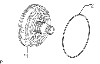
Coat a new oil pump O-ring with ATF, and install it to the oil pump assembly.
Text in Illustration *1 Oil Pump Assembly *2 Oil Pump O-ring
 |
Clean and degrease the threads of the 11 bolts and the contact surfaces of the automatic transmission case sub-assembly and the oil pump assembly with non-residue solvent.
- NOTICE:
- During installation, do not allow oil to contact the bolts or the surface of the oil pump assembly body.
Place the oil pump assembly through the input shaft, and align the bolt holes of the oil pump assembly with the automatic transmission case sub-assembly.
Hold the input shaft, and lightly press the oil pump assembly to slide the oil seal rings into the front planetary gear assembly.
- NOTICE:
- Be careful not to damage the O-ring and oil seal rings.
Install the 11 bolts.
- Torque:
- 25 N*m{250 kgf*cm, 18 ft.*lbf}
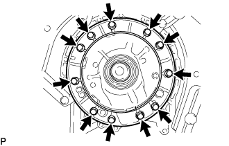 |
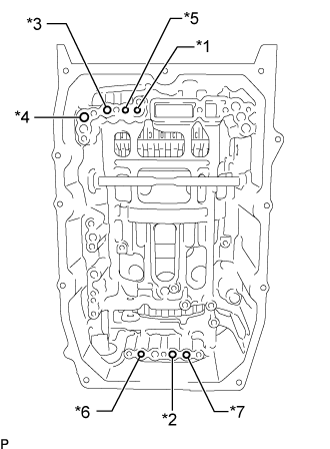
| 38. INSPECT INDIVIDUAL PISTON OPERATION |
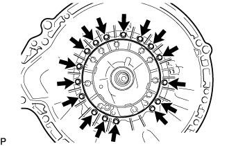
Check the operating sound while applying compressed air into the oil holes indicated in the illustration.
Text in Illustration *1 Forward Clutch *2 Direct Clutch *3 Overdrive Clutch *4 Reverse Clutch *5 No. 1 Brake *6 No. 2 Brake (IN) *7 No. 2 Brake (OUT)
 |
| 39. INSTALL MANUAL DETENT SPRING SUB-ASSEMBLY |
Install the manual detent spring sub-assembly and manual detent spring cover with the bolt.
- Torque:
- 10 N*m{102 kgf*cm, 7 ft.*lbf}
Text in Illustration *1 Manual Detent Spring Sub-assembly *2 Manual Detent Spring Cover
 |
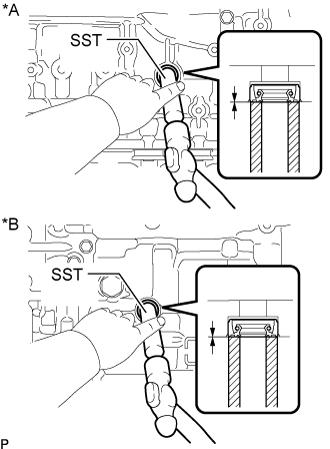
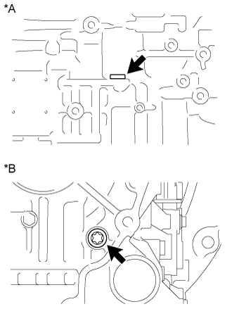
| 40. INSTALL MANUAL VALVE LEVER SHAFT OIL SEAL |
Using SST and a hammer, tap in 2 new manual valve lever shaft oil seals.
- SST
- 09350-30020(09350-07110)
- Standard depth:
- -0.2 to 0.4 mm (-0.00788 to 0.0157 in.)
Text in Illustration *A for RH Side *B for LH Side
 |
Coat the lip of the 2 manual valve lever shaft oil seals with MP grease.
| 41. INSTALL PARKING LOCK PAWL SHAFT |
Install the E-ring to the parking lock pawl shaft.
Text in Illustration *1 Parking Lock Pawl *2 Parking Lock Pawl Shaft *3 Spring *4 E-ring
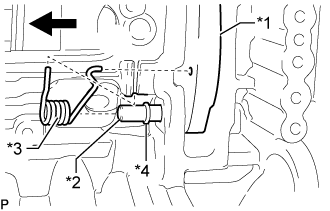 |
Install the parking lock pawl, parking lock pawl shaft and spring.
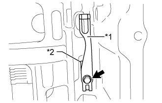
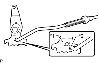
| 42. INSTALL PARKING LOCK ROD SUB-ASSEMBLY |
Connect the parking lock rod sub-assembly to the manual valve lever sub-assembly.
Text in Illustration *1 Manual Valve Lever Sub-assembly *2 Parking Lock Rod Sub-assembly
 |
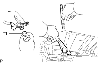
| 43. INSTALL MANUAL VALVE LEVER SUB-ASSEMBLY |
Install a new spacer to the manual valve lever sub-assembly.
Text in Illustration *1 Spacer
 |
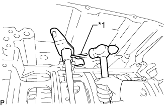
Install the manual valve lever shaft to the manual valve lever sub-assembly and automatic transmission case sub-assembly.
Using a hammer, install a new spring pin.
Text in Illustration *1 Spring Pin
 |
Turn the spacer and manual valve lever shaft to align the smaller hole on the spacer with the indent on the manual valve lever sub-assembly.
Using a 3 mm pin punch and a hammer, stake the spacer.
 |
Check that the spacer does not turn.
| 44. INSTALL PARKING LOCK PAWL BRACKET |
Install the parking lock pawl bracket to the automatic transmission case sub-assembly with the 3 bolts, in several steps in the order shown in the illustration.
- Torque:
- 18 N*m{184 kgf*cm, 13 ft.*lbf}
 |
Move the manual valve lever sub-assembly to the P position, and check the output shaft sub-assembly is locked by the parking lock pawl.
 |
| 45. INSTALL TRANSMISSION REVOLUTION SENSOR (SP2) |
Install the transmission revolution sensor (SP2) to the automatic transmission case sub-assembly with the bolt.
- Torque:
- 5.5 N*m{56 kgf*cm, 49 in.*lbf}
Connect the connector to the transmission revolution sensor (SP2).
Install the wire harness clamp with the bolt.
- Torque:
- 5.5 N*m{56 kgf*cm, 49 in.*lbf}
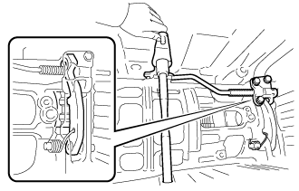
| 46. INSTALL TRANSMISSION WIRE |
Coat the O-ring with ATF.
Install the transmission wire with the bolt.
- Torque:
- 5.5 N*m{56 kgf*cm, 49 in.*lbf}
Connect the transmission wire connector.
- HINT:
- Push up the lever until the claw of the transmission wire connector makes a connection sound.
 |
Install the wire harness clamp with the bolt.
- Torque:
- 5.5 N*m{56 kgf*cm, 49 in.*lbf}
Connect the connector to the transmission revolution sensor (SP2).
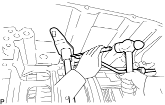
| 47. INSTALL TRANSMISSION VALVE BODY ASSEMBLY |
Insert the manual valve lever sub-assembly into the groove on the end of the manual valve and install the transmission valve body assembly to the automatic transmission case sub-assembly with the 14 bolts.
- Torque:
- 8.0 N*m{82 kgf*cm, 71 in.*lbf}
Text in Illustration *1 Manual Valve Lever Sub-assembly *2 Manual Valve - Bolt Length:
Item Specified Condition Bolt A 28 mm (1.10 in.) Bolt B 40 mm (1.57 in.)
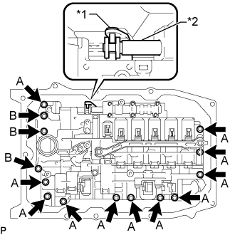 |
Mark the top of each bolt with paint.
Retighten the 14 bolts an additional 90°.
Check that the paint marks are now at a 90° angle to the top.
Connect the 9 connectors to the solenoid valves.
Connect the transmission revolution sensor (NT) connector.
Coat the temperature sensor O-ring with ATF.
Install the ATF temperature sensor and lock plate with the bolt.
- Torque:
- 10 N*m{102 kgf*cm, 7 ft.*lbf}
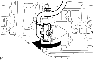
| 48. INSTALL VALVE BODY OIL STRAINER ASSEMBLY |
Remove the 4 bolts and valve body oil strainer assembly from the transmission valve body assembly.
- NOTICE:
- Be careful as some fluid will come out of the valve body oil strainer assembly.
 |
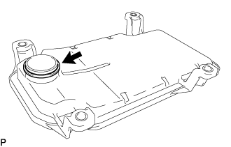
Remove the O-ring from the valve body oil strainer assembly.
 |
| 49. INSTALL AUTOMATIC TRANSMISSION OIL PAN SUB-ASSEMBLY |
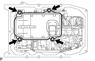
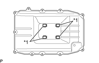
Install the 4 transmission oil cleaner magnets to the automatic transmission oil pan sub-assembly.
Text in Illustration *1 Transmission Oil Cleaner Magnet
 |
Install a new automatic transmission oil pan gasket and the automatic transmission oil pan sub-assembly to the automatic transmission case sub-assembly with the 11 bolts.
- Torque:
- 7.5 N*m{76 kgf*cm, 66 in.*lbf}
- NOTICE:

- Make sure that there is no oil or foreign matter on the gasket seal surface and automatic transmission oil pan sub-assembly contact surface.
- Install the gasket so that there is no slack in the gasket, and that the entire circumference of the seal surface is level.
- Make sure that the 11 gasket drop prevention protrusions are set on the automatic transmission oil pan sub-assembly.
- When tightening the automatic transmission oil pan sub-assembly, make sure that the gasket is not pinched between the sleeve of the gasket tightening area and the seal surface of the transmission.
Text in Illustration *1 Sleeve *2 Automatic Transmission Case Sub-assembly *a Correct *b Incorrect *c Protrusion
| 50. INSTALL AUTOMATIC TRANSMISSION CASE PLUG |
for T55H "TORX" Type:
Text in Illustration *A for LH Side *B for Rear Side Install the 2 new O-rings to the 2 automatic transmission case plugs.
Using a T55H "TORX" socket wrench, install the 2 automatic transmission case plugs to the automatic transmission case sub-assembly.
- Torque:
- 40 N*m{403 kgf*cm, 30 ft.*lbf}
 |
for 17 mm Hexagon Type:
Install a new O-ring to the automatic transmission case plug.
Install the automatic transmission case plug to the automatic transmission case sub-assembly.
- Torque:
- 80 N*m{816 kgf*cm, 59 ft.*lbf}
 |
| 51. INSTALL REFILL PLUG |
Install a new O-ring to the refill plug.
Install the refill plug.
- Torque:
- 39 N*m{400 kgf*cm, 29 ft.*lbf}
| 52. INSTALL OIL COOLER TUBE UNION |
Install the 2 new O-rings to the 2 oil cooler tube unions.
Using SST, install the 2 oil cooler tube unions to the automatic transmission case sub-assembly.
- SST
- 09268-78010
- Torque:
- Specified tightening torque:
- 29 N*m{300 kgf*cm, 22 ft.*lbf}
Text in Illustration *a Torque Wrench Fulcrum Length *b 18 to 22° *c 43 to 47° - HINT:
- Calculate the torque wrench reading when changing the fulcrum length of the torque wrench (Click here).
- When using SST (fulcrum length of 34.5 mm (1.3583 in.)) + torque wrench (fulcrum length of 180 mm (7.0866 in.)): 25 N*m (252 kgf*cm, 18 ft.*lbf)
 |
| 53. INSTALL PARK/NEUTRAL POSITION SWITCH ASSEMBLY |
- HINT:
- Make sure that the manual valve lever shaft has not been rotated prior to installing the park/neutral position switch assembly as the detent spring may become detached from the manual valve lever shaft.
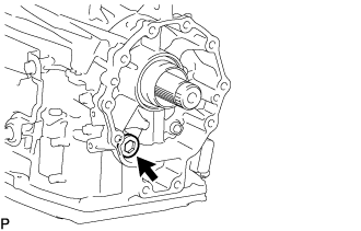
Install the park/neutral position switch assembly to the manual valve lever shaft.
Temporarily install the park/neutral position switch assembly with the 2 bolts.
- HINT:
- Tighten the bolt to the specified torque when adjusting the park/neutral position switch assembly.
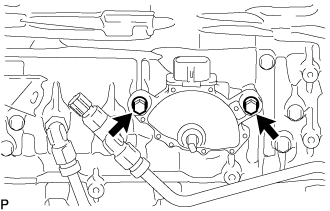 |
Install the lock washer and the nut.
- Torque:
- 6.9 N*m{70 kgf*cm, 61 in.*lbf}
Install the No. 1 shift lever bush to the transmission control shaft lever.
Install the bush to the transmission control shaft lever.
Temporarily install the transmission control shaft lever.
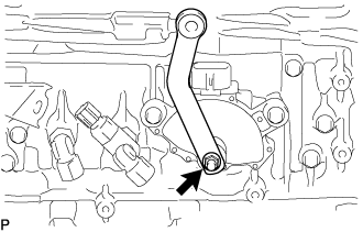 |
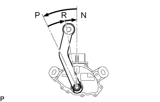
Turn the transmission control shaft lever counterclockwise until it stops, and then turn it clockwise 2 notches to set it to the N position.
 |
Remove the transmission control shaft lever.
Align the groove with the neutral basic line.
Text in Illustration *a Neutral Basic line *b Groove
 |
Hold the park/neutral position switch assembly in the position described above and tighten the 2 bolts.
- Torque:
- 5.4 N*m{55 kgf*cm, 48 in.*lbf}
|
Using a screwdriver, bend the tabs of the lock washer.
Text in Illustration *a Protective Tape
 |
Install the transmission control shaft lever with the spring washer and nut.
- Torque:
- 16 N*m{163 kgf*cm, 12 ft.*lbf}
|
Connect the switch connector.
| 54. INSTALL REAR TRANSFER ADAPTER |
Coat a new O-ring with ATF and install it to the rear transfer adapter.
Install the rear transfer adapter with the 10 bolts.
- Torque:
- 34 N*m{345 kgf*cm, 25 ft.*lbf}
 |
| 55. INSTALL TRANSFER CASE ADAPTER REAR OIL SEAL |
Coat the lip of a new transfer case adapter rear oil seal with MP grease.
Using SST and a hammer, tap in the transfer case adapter rear oil seal.
- SST
- 09223-50010
09710-30031(09710-03171)
- Standard depth:
- 0 to 1 mm (0 to 0.0393 in.)
 |
| 56. INSTALL AUTOMATIC TRANSMISSION HOUSING |
Remove the automatic transmission assembly from the overhaul attachment.
 |
Install the automatic transmission housing to the automatic transmission case sub-assembly with the 16 bolts.
- Torque:
- 25 N*m{250 kgf*cm, 18 ft.*lbf}
 |
| 57. INSTALL TRANSMISSION BREATHER HOSE SUB-ASSEMBLY |
Coat a new breather plug O-ring with ATF, and install it to the No. 1 breather plug.
Text in Illustration *1 No. 2 Breather Plug *2 No. 1 Breather Plug *3 Breather Plug Hose *4 Clamp *5 Breather Plug O-ring - NOTICE:
- Ensure that the breather plug O-ring is not twisted.
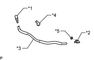 |
Install the No. 1 breather plug and No. 2 breather plug to the breather plug hose.
Install the clamp to the breather plug hose.
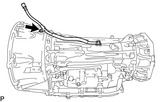
Install the transmission breather hose sub-assembly to the automatic transmission case sub-assembly with the bolt.
- Torque:
- 5.4 N*m{55 kgf*cm, 48 in.*lbf}
 |