Automatic Transmission Unit Inspection
Drivetrain. Land Cruiser. Urj200, 202 Grj200 Vdj200
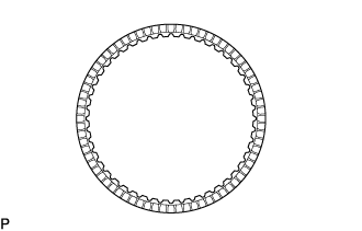
INSPECT NO. 1 BRAKE DISC
INSPECT FRONT PLANETARY GEAR ASSEMBLY
INSPECT PACK CLEARANCE OF NO. 1 BRAKE
INSPECT NO. 3 CLUTCH DISC
INSPECT PACK CLEARANCE OF NO. 3 CLUTCH
INSPECT OVERDRIVE DIRECT CLUTCH DISC
INSPECT REVERSE CLUTCH RETURN SPRING SUB-ASSEMBLY (REAR)
INSPECT PACK CLEARANCE OF OVERDRIVE DIRECT CLUTCH
INSPECT REVERSE CLUTCH RETURN SPRING SUB-ASSEMBLY (FRONT)
INSPECT REVERSE CLUTCH DRUM SUB-ASSEMBLY
INSPECT FORWARD MULTIPLE CLUTCH DISC
INSPECT FORWARD CLUTCH RETURN SPRING SUB-ASSEMBLY
INSPECT PACK CLEARANCE OF FORWARD MULTIPLE CLUTCH
INSPECT FORWARD CLUTCH DRUM SUB-ASSEMBLY
INSPECT SUN GEAR INPUT DRUM SUB-ASSEMBLY
INSPECT REAR PLANETARY SUN GEAR SUB-ASSEMBLY
INSPECT REAR PLANETARY GEAR ASSEMBLY
INSPECT NO. 1 ONE-WAY CLUTCH
INSPECT NO. 2 BRAKE DISC
INSPECT NO. 2 CLUTCH DISC
INSPECT NO. 2 BRAKE PISTON RETURN SPRING SUB-ASSEMBLY
INSPECT PACK CLEARANCE OF NO. 2 BRAKE
INSPECT DIRECT CLUTCH RETURN SPRING SUB-ASSEMBLY
INSPECT PACK CLEARANCE OF NO. 2 CLUTCH
INSPECT INDIVIDUAL PISTON OPERATION
INSPECT AUTOMATIC TRANSMISSION CASE SUB-ASSEMBLY
Automatic Transmission Unit -- Inspection |
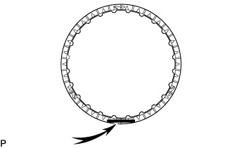
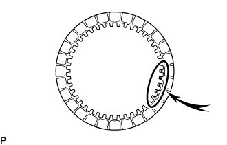
| 1. INSPECT NO. 1 BRAKE DISC |
Check whether the sliding surfaces of the No. 1 brake discs, No. 1 brake plates and the No. 1 brake flange are worn or burnt.
- NOTICE:
- If the linings of the No. 1 brake discs are peeled off or discolored, or if any part of the printed numbers is damaged, replace all the No. 1 brake discs.
- Before assembling new No. 1 brake discs, soak them in ATF for at least 2 hours.
If necessary, replace them.
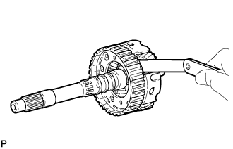
| 2. INSPECT FRONT PLANETARY GEAR ASSEMBLY |
Using a feeler gauge, measure the clearance between the front planetary gear assembly and each pinion gear.
- Standard Clearance:
- 0.2 to 0.6 mm (0.00788 to 0.0236 in.)
If the clearance is not as specified, replace the front planetary gear assembly.
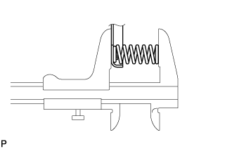
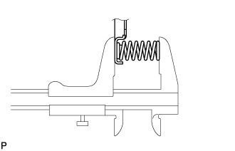
| 3. INSPECT PACK CLEARANCE OF NO. 1 BRAKE |
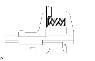
Using a vernier caliper, measure dimension A (from the step of the oil pump assembly installation surface of the automatic transmission case sub-assembly to the step of the No. 1 brake flange installation surface) in the illustration, and calculate the average.
Text in Illustration*1
| Snap Ring
|
- HINT:
- Dimension A = 46.18 to 46.54 mm (1.8182 to 1.8322 in.)
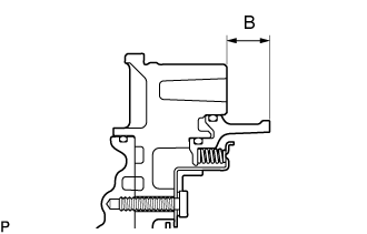
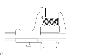
Using a vernier caliper, measure dimension B (from the flange face of the oil pump assembly to the tip of the No. 1 brake piston) in the illustration, and calculate the average.
- HINT:
- Dimension B = 19.23 to 19.57 mm (0.7571 to 0.7704 in.)
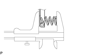
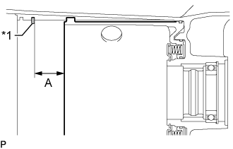
Using a vernier caliper, assemble the 6 No. 1 brake plates, 6 No. 1 brake discs and No. 1 brake flange, measure dimension C in the illustration and calculate the average.
Text in Illustration*1
| No. 1 Brake Flange
|
*2
| No. 1 Brake Disc
|
*3
| No. 1 Brake Plate
|
- HINT:
- Dimension C = 25.15 to 26.45 mm (0.9902 to 1.0413 in.)
- Pack clearance = Dimension A - Dimension B - Dimension C
- Standard Clearance:
- 0.90 to 1.10 mm (0.0355 to 0.0433 in.)
If the pack clearance is outside the standard range, select and install a No. 1 brake flange that brings the pack clearance within the standard range.
- HINT:
- There are 7 types of No. 1 brake flanges that can be used to adjust the pack clearance. Select the one with the most appropriate thickness.
- No. 1 Brake Flange Thickness:
Part No.
| Mark
| Thickness
|
35676-60190
| 0
| 4.45 to 4.55 mm (0.1752 to 0.1791 in.)
|
35676-60200
| 1
| 4.55 to 4.65 mm (0.1792 to 0.1830 in.)
|
35676-60210
| 2
| 4.65 to 4.75 mm (0.1831 to 0.1870 in.)
|
35676-60220
| 3
| 4.75 to 4.85 mm (0.1871 to 0.1909 in.)
|
35676-60230
| 4
| 4.85 to 4.95 mm (0.1910 to 0.1948 in.)
|
35676-60240
| 5
| 4.95 to 5.05 mm (0.1949 to 0.1988 in.)
|
35676-60250
| 6
| 5.05 to 5.15 mm (0.1989 to 0.2027 in.)
|
| 4. INSPECT NO. 3 CLUTCH DISC |
Check whether the sliding surfaces of the No. 3 clutch discs, No. 3 clutch plates and the No. 3 clutch flange are worn or burnt.
- NOTICE:
- If the linings of the No. 3 clutch discs are peeled off or discolored, or if any part of the printed numbers is damaged, replace all the No. 3 clutch discs.
- Before assembling new No. 3 clutch discs, soak them in ATF for at least 2 hours.
If necessary, replace them.
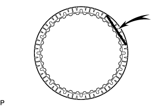
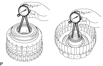
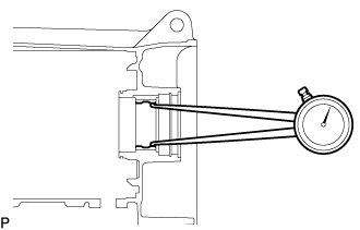
| 5. INSPECT PACK CLEARANCE OF NO. 3 CLUTCH |
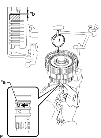
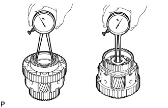
Using a dial indicator, measure the moving distance (distance A) of the No. 3 clutch flange at both ends across the diameter while blowing compressed air (196 kPa, 2.0 kgf/cm2, 28 psi) from the oil hole as shown in the illustration, and calculate the average.
Text in Illustration*a
| Oil Hole
| *b
| Distance A
|
*c
| Speed Sensor Hole
| -
| -
|
- Standard Clearance:
- 0.90 to 1.10 mm (0.0355 to 0.0433 in.)
If the pack clearance is outside the standard range, select and install a No. 3 clutch flange that brings the pack clearance within the standard range.
- HINT:
- There are 11 types of No. 3 clutch flanges that can be used to adjust the pack clearance. Select the one with the most appropriate thickness.
- No. 3 Clutch Flange Thickness:
Part No.
| Thickness
|
34649-60250
| 3.75 to 3.85 mm (0.1477 to 0.1515 in.)
|
34649-60260
| 3.85 to 3.95 mm (0.1516 to 0.1555 in.)
|
34649-60270
| 3.95 to 4.05 mm (0.1556 to 0.1594 in.)
|
34649-60280
| 4.05 to 4.15 mm (0.1595 to 0.1633 in.)
|
34649-60290
| 4.15 to 4.25 mm (0.1634 to 0.1673 in.)
|
34649-60300
| 4.25 to 4.35 mm (0.1674 to 0.1712 in.)
|
34649-60310
| 4.35 to 4.45 mm (0.1713 to 0.1751 in.)
|
34649-60320
| 4.45 to 4.55 mm (0.1752 to 0.1791 in.)
|
34649-60330
| 4.55 to 4.65 mm (0.1792 to 0.1830 in.)
|
34649-60340
| 4.65 to 4.75 mm (0.1831 to 0.1870 in.)
|
34649-60350
| 4.75 to 4.85 mm (0.1871 to 0.1909 in.)
|
| 6. INSPECT OVERDRIVE DIRECT CLUTCH DISC |
Check whether the sliding surfaces of the overdrive direct clutch discs, overdrive direct clutch plates and the overdrive clutch flange are worn or burnt.
- NOTICE:
- If the linings of the overdrive direct clutch discs are peeled off or discolored, or if any part of the printed numbers is damaged, replace all the overdrive direct clutch discs.
- Before assembling new overdrive direct clutch discs, soak them in ATF for at least 2 hours.
If necessary, replace them.
| 7. INSPECT REVERSE CLUTCH RETURN SPRING SUB-ASSEMBLY (REAR) |
Using a vernier caliper, measure the free length of the spring together with the spring seat.
- Standard Free Length:
- 22.21 mm (0.874 in.)
If the free length is shorter than the standard free length, replace the reverse clutch return spring sub-assembly (rear).
| 8. INSPECT PACK CLEARANCE OF OVERDRIVE DIRECT CLUTCH |
Using a dial indicator, measure the moving distance (distance A) of the reverse clutch flange at both ends across the diameter while blowing compressed air (300 kPa, 3.1 kgf/cm2, 44 psi) from the oil hole as shown in the illustration, and calculate the average.
Text in Illustration*a
| Oil Hole
| *b
| Distance A
|
*c
| Speed Sensor Hole
| -
| -
|
- Standard Clearance:
- 1.19 to 1.39 mm (0.0469 to 0.0547 in.)
If the pack clearance is outside the standard range, select and install a overdrive clutch flange that brings the pack clearance within the standard range.
- HINT:
- There are 11 types of overdrive clutch flanges that can be used to adjust the pack clearance. Select the one with the most appropriate thickness.
- Overdrive Clutch Flange Thickness:
Part No.
| Thickness
|
34615-60010
| 2.85 to 2.95 mm (0.1123 to 0.1161 in.)
|
34615-60020
| 2.95 to 3.05 mm (0.1162 to 0.1200 in.)
|
34615-60030
| 3.05 to 3.15 mm (0.1201 to 0.1240 in.)
|
34615-60040
| 3.15 to 3.25 mm (0.1241 to 0.1279 in.)
|
34615-60050
| 3.25 to 3.35 mm (0.1280 to 0.1318 in.)
|
34615-60060
| 3.35 to 3.45 mm (0.1319 to 0.1358 in.)
|
34615-60070
| 3.45 to 3.55 mm (0.1359 to 0.1397 in.)
|
34615-60080
| 3.55 to 3.65 mm (0.1398 to 0.1437 in.)
|
34615-60090
| 3.65 to 3.75 mm (0.1438 to 0.1476 in.)
|
34615-60100
| 3.75 to 3.85 mm (0.1477 to 0.1515 in.)
|
34615-60110
| 3.85 to 3.95 mm (0.1516 to 0.1555 in.)
|
| 9. INSPECT REVERSE CLUTCH RETURN SPRING SUB-ASSEMBLY (FRONT) |
Using a vernier caliper, measure the free length of the spring together with the spring seat.
- Standard Free Length:
- 21.59 mm (0.850 in.)
If the free length is shorter than the standard free length, replace the reverse clutch return spring sub-assembly (front).
| 10. INSPECT REVERSE CLUTCH DRUM SUB-ASSEMBLY |
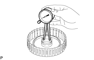
Using a caliper gauge, measure the inside diameter of the reverse clutch drum sub-assembly bush.
- Standard Inside Diameter (Front Side):
- 67.40 to 67.44 mm (2.6536 to 2.6551 in.)
- Standard Inside Diameter (Rear Side):
- 55.62 to 55.64 mm (2.1898 to 2.1905 in.)
If the inside diameter is not as specified, replace the reverse clutch drum sub-assembly.
| 11. INSPECT FORWARD MULTIPLE CLUTCH DISC |
Check whether the sliding surfaces of the forward multiple clutch discs, forward multiple clutch plates and forward clutch flange are worn or burnt.
- NOTICE:
- If the linings of the forward multiple clutch discs are peeled off or discolored, replace all the forward multiple clutch discs.
- Before assembling new forward multiple clutch discs, soak them in ATF for at least 2 hours.
If necessary, replace them.
| 12. INSPECT FORWARD CLUTCH RETURN SPRING SUB-ASSEMBLY |
Using a vernier caliper, measure the free length of the spring together with the spring seat.
- Standard Free Length:
- 20.82 mm (0.820 in.)
If the free length is shorter than the standard free length, replace the forward clutch return spring sub-assembly.
| 13. INSPECT PACK CLEARANCE OF FORWARD MULTIPLE CLUTCH |
Temporarily assemble the front planetary gear assembly to the forward clutch drum sub-assembly.
Using a dial indicator, measure the moving distance (distance A) of the forward clutch flange at both ends across the diameter while blowing compressed air (196 kPa, 2.0 kgf/cm2, 28 psi) from the oil hole as shown in the illustration, and calculate the average.
Text in Illustration*a
| Oil Hole
|
*b
| Distance A
|
- Standard Clearance:
- 1.05 to 1.25 mm (0.0414 to 0.0492 in.)
If the pack clearance is outside the standard range, select and install a forward clutch flange that brings the pack clearance within the standard range.
- HINT:
- There are 9 types of forward clutch flanges that can be used to adjust the pack clearance. Select the one with the most appropriate thickness.
- Forward Clutch Flange Thickness:
Part No.
| Mark
| Thickness
|
35635-50090
| 0
| 4.35 to 4.45 mm (0.1713 to 0.1751 in.)
|
35635-50100
| 1
| 4.45 to 4.55 mm (0.1752 to 0.1791 in.)
|
35635-50110
| 2
| 4.55 to 4.65 mm (0.1792 to 0.1830 in.)
|
35635-50120
| 3
| 4.65 to 4.75 mm (0.1831 to 0.1870 in.)
|
35635-50130
| 4
| 4.75 to 4.85 mm (0.1871 to 0.1909 in.)
|
35635-50140
| 5
| 4.85 to 4.95 mm (0.1910 to 0.1948 in.)
|
35635-50150
| 6
| 4.95 to 5.05 mm (0.1949 to 0.1988 in.)
|
35635-50160
| 7
| 5.05 to 5.15 mm (0.1989 to 0.2027 in.)
|
35635-50170
| 8
| 5.15 to 5.25 mm (0.2028 to 0.2066 in.)
|
| 14. INSPECT FORWARD CLUTCH DRUM SUB-ASSEMBLY |
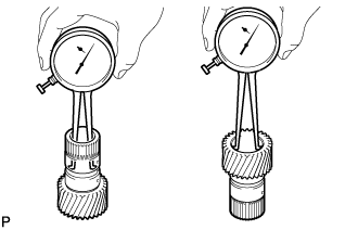
Using a caliper gauge, measure the inside diameter of the forward clutch drum bush.
- Standard Inside Diameter:
- 33.200 to 33.225 mm (1.3071 to 1.3080 in.)
If the inside diameter is not as specified, replace the forward clutch drum sub-assembly.
| 15. INSPECT SUN GEAR INPUT DRUM SUB-ASSEMBLY |
Using a caliper gauge, measure the inside diameter of the sun gear input drum bush.
- Standard Inside Diameter:
- 45.066 to 45.091 mm (1.7743 to 1.7752 in.)
If the inside diameter is not as specified, replace the sun gear input drum sub-assembly.
| 16. INSPECT REAR PLANETARY SUN GEAR SUB-ASSEMBLY |
Using a caliper gauge, measure the inside diameter of the rear planetary sun gear bush.
- Standard Inside Diameter:
- 28.760 to 28.781 mm (1.1323 to 1.1331 in.)
If the inside diameter is not as specified, replace the rear planetary sun gear sub-assembly.
| 17. INSPECT REAR PLANETARY GEAR ASSEMBLY |
Using a feeler gauge, measure the rear planetary gear pinion long and short thrust clearance.
- Standard Clearance:
- 0.2 to 0.6 mm (0.00788 to 0.0236 in.)
If the clearance is not as specified, replace the rear planetary gear assembly.
Using a caliper gauge, measure the inside diameter of the rear planetary gear bush.
- Standard Inside Diameter (Front Side):
- 70.60 to 70.63 mm (2.7796 to 2.7807 in.)
- Standard Inside Diameter (Rear Side):
- 28.700 to 28.721 mm (1.1300 to 1.1307 in.)
If the inside diameter is not as specified, replace the rear planetary gear assembly.
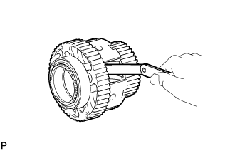
| 18. INSPECT NO. 1 ONE-WAY CLUTCH |
Install the No. 1 one-way clutch to the rear planetary gear assembly.
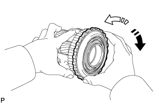
Hold the rear planetary gear assembly and turn the No. 1 one-way clutch.
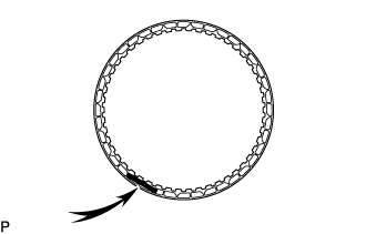
Text in Illustration
| Lock
|

| Free
|
Check that the No. 1 one-way clutch turns freely counterclockwise and locks clockwise.
If the No. 1 one-way clutch does not operate normally, replace it.
| 19. INSPECT NO. 2 BRAKE DISC |
Check whether the sliding surfaces of the No. 2 brake discs, brake plate, No. 2 brake plates and the No. 2 brake flange are worn or burnt.
- NOTICE:
- If the linings of the No. 2 brake discs are peeled off or discolored, or if any part of the printed numbers is damaged, replace all the No. 2 brake discs.
- Before assembling new discs, soak them in ATF for at least 2 hours.
If necessary, replace them.
| 20. INSPECT NO. 2 CLUTCH DISC |
Check whether the sliding surfaces of the No. 2 clutch discs, No. 2 clutch plates and the No. 2 clutch flange are worn or burnt.
- NOTICE:
- If the linings of the No. 2 clutch discs are peeled off or discolored, replace all the No. 2 clutch discs.
- Before assembling new discs, soak them in ATF for at least 2 hours.
If necessary, replace them.
| 21. INSPECT NO. 2 BRAKE PISTON RETURN SPRING SUB-ASSEMBLY |
Using a vernier caliper, measure the free length of the spring together with the spring seat.
- Standard Free Length:
- 23.36 mm (0.920 in.)
If the free length is shorter than the standard free length, replace the No. 2 brake piston return spring sub-assembly.
| 22. INSPECT PACK CLEARANCE OF NO. 2 BRAKE |
Using a vernier caliper, measure dimension A (from the tip of the No. 2 brake piston to the step in the automatic transmission case sub-assembly) in the illustration, and calculate the average.
Text in Illustration*1
| Snap Ring
|
- HINT:
- Dimension A = 35.75 to 36.25 mm (1.4075 to 1.4271 in.)
Using a vernier caliper, assemble the 6 No. 2 brakes discs, brake plate, 5 No. 2 brake plates and No. 2 brake flange as shown in the illustration. Then with a weight fixture of 500 g (17.64 oz) or less placed on the flange, measure dimension B, and calculate the average.
Text in Illustration*1
| No. 2 Brake Flange
|
*2
| Brake Plate
|
*3
| No. 2 Brake Plate
|
*4
| No. 2 Brake Disc
|
*a
| Weight
|
- HINT:
- Dimension B = 33.73 to 35.07 mm (1.3280 to 1.3807 in.)
- Pack clearance = Dimension A - Dimension B
- Standard Clearance:
- 0.90 to 2.18 mm (0.0355 to 0.0858 in.)
If the pack clearance is outside the standard range, select and install a No. 2 brake flange that brings the pack clearance within the standard range.
- HINT:
- There are 11 types of No. 2 brake flanges that can be used to adjust the pack clearance. Select the one with the most appropriate thickness.
- No. 2 Brake Flange Thickness:
Part No.
| Mark
| Thickness
|
35678-60190
| 
| 9.75 to 9.85 mm (0.3839 to 0.3877 in.)
|
35678-60200
| 
| 9.85 to 9.95 mm (0.3878 to 0.3917 in.)
|
35678-60210
| 
| 9.95 to 10.05 mm (0.3918 to 0.3956 in.)
|
35678-60220
| 
| 10.05 to 10.15 mm (0.3957 to 0.3996 in.)
|
35678-60230
| 
| 10.15 to 10.25 mm (0.3997 to 0.4035 in.)
|
35678-60240
| 
| 10.25 to 10.35 mm (0.4036 to 0.4074 in.)
|
35678-60250
| 
| 10.35 to 10.45 mm (0.4075 to 0.4114 in.)
|
35678-60260
| 
| 10.45 to 10.55 mm (0.4115 to 0.4153 in.)
|
35678-60270
| 
| 10.55 to 10.65 mm (0.4154 to 0.4192 in.)
|
35678-60280
| 
| 10.65 to 10.75 mm (0.4193 to 0.4232 in.)
|
35678-60290
| 
| 10.75 to 10.85 mm (0.4233 to 0.4271 in.)
|
| 23. INSPECT DIRECT CLUTCH RETURN SPRING SUB-ASSEMBLY |
Using a vernier caliper, measure the free length of the spring together with the spring seat.
- Standard Free Length:
- 20.76 mm (0.817 in.)
If the free length is shorter than the standard free length, replace the direct clutch return spring sub-assembly.
| 24. INSPECT PACK CLEARANCE OF NO. 2 CLUTCH |
Using a dial indicator, measure the moving distance (distance A) of the No. 2 clutch flange at both ends across the diameter while blowing compressed air (196 kPa, 2.0 kgf/cm2, 28 psi) from the oil hole as shown in the illustration, and calculate the average.
- Standard Clearance:
- 1.05 to 1.25 mm (0.0414 to 0.0492 in.)
Text in Illustration*a
| Oil Hole
|
*b
| Distance A
|
If the pack clearance is outside the standard range, select and install a No. 2 clutch flange that brings the pack clearance within the standard range.
- HINT:
- There are 9 types of No. 2 clutch flanges that can be used to adjust the pack clearance. Select the one with the most appropriate thickness.
- No. 2 Clutch Flange Thickness:
Part No.
| Mark
| Thickness
|
35635-50181
| 40
| 3.95 to 4.05 mm (0.1556 to 0.1594 in.)
|
35635-50231
| 41
| 4.05 to 4.15 mm (0.1595 to 0.1633 in.)
|
35635-50191
| 42
| 4.15 to 4.25 mm (0.1634 to 0.1673 in.)
|
35635-50241
| 43
| 4.25 to 4.35 mm (0.1674 to 0.1712 in.)
|
35635-50201
| 44
| 4.35 to 4.45 mm (0.1713 to 0.1751 in.)
|
35635-50251
| 45
| 4.45 to 4.55 mm (0.1752 to 0.1791 in.)
|
35635-50211
| 46
| 4.55 to 4.65 mm (0.1792 to 0.1830 in.)
|
35635-50261
| 47
| 4.65 to 4.75 mm (0.1831 to 0.1870 in.)
|
35635-50221
| 48
| 4.75 to 4.85 mm (0.1871 to 0.1909 in.)
|
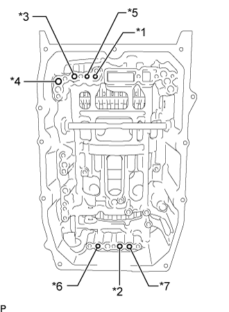
| 25. INSPECT INDIVIDUAL PISTON OPERATION |
Check the operating sound while applying compressed air into the oil holes indicated in the illustration.
Text in Illustration*1
| Forward Clutch
|
*2
| Direct Clutch
|
*3
| Overdrive Clutch
|
*4
| Reverse Clutch
|
*5
| No. 1 Brake
|
*6
| No. 2 Brake (IN)
|
*7
| No. 2 Brake (OUT)
|
| 26. INSPECT AUTOMATIC TRANSMISSION CASE SUB-ASSEMBLY |
Using a caliper gauge, measure the inside diameter of the automatic transmission case sleeve bush.
- Standard Inside Diameter:
- 51.470 to 51.555 mm (2.027 to 2.029 in.)
If the inside diameter is not as specified, replace the automatic transmission case sub-assembly.