Dtc B2799 Engine Immobiliser System Malfunction
DESCRIPTION
WIRING DIAGRAM
INSPECTION PROCEDURE
CLEAR DTC
CHECK FOR DTC
REGISTER ECU COMMUNICATION ID
CHECK WHETHER ENGINE STARTS
REPLACE ECM
CHECK WHETHER ENGINE STARTS
CHECK HARNESS AND CONNECTOR (TRANSPONDER KEY ECU ASSEMBLY - ECM)
DTC B2799 Engine Immobiliser System Malfunction |
DESCRIPTION
The ECM stores this DTC when the communication line between the ECM and transponder key ECU assembly is malfunctioning or the communication ID of the ECM and transponder key ECU assembly do not match.DTC No.
| DTC Detection Condition
| Trouble Area
| DTC Output Confirmation Operation
|
B2799
| One of the following conditions is met:
- Error in communication between ECM and transponder key ECU assembly.
- Error in communication lines.
- Communication ID is different during communication between ECM and transponder key ECU assembly.
| - Wire harness or connector
- Transponder key ECU
- ECM
| - Start the engine and wait 10 seconds.*1
- After disconnecting and reconnecting the cable to the negative (-) battery terminal, turn the ignition switch to ON and wait 10 seconds.*2
*1: Communication starts within 3 seconds of starting the engine. If verification fails, this DTC is stored 6 seconds after communication has completed.
*2: Communication starts within 3 seconds of turning the ignition switch to ON. If verification fails, this DTC is stored 6 seconds after communication has completed.
|
Vehicle Condition and Fail-safe Operation when Malfunction DetectedVehicle Condition when Malfunction Detected
| Fail-safe Operation when Malfunction Detected
|
Engine cannot be started
| -
|
Related Data List and Active TestDTC No.
| Data List and Active Test
|
B2799
| -
|
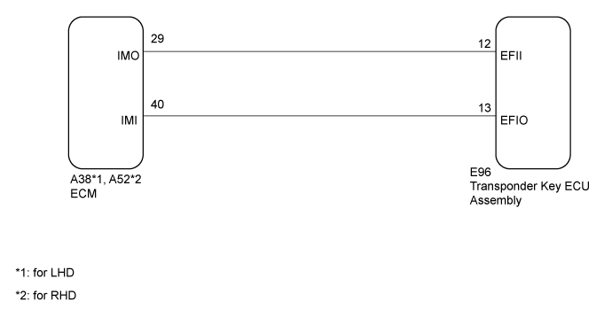
WIRING DIAGRAM
INSPECTION PROCEDURE
- NOTICE:
- If the transponder key ECU assembly or ECM is replaced, refer to Service Bulletin.
- After repair, confirm that no DTCs are output by performing "DTC Output Confirmation Operation".
- When using the GTS with the vehicle ignition switch off, connect the GTS to the vehicle and turn a courtesy light switch on and off at intervals of 1.5 seconds or less until communication between the GTS and the vehicle begins. Then select the Model Code "KEY REGIST" under manual mode and enter the following menus: Body Electrical / Immobiliser. While using the GTS, periodically turn a courtesy light switch on and off at intervals of 1.5 seconds or less to maintain communication between the GTS and the vehicle.
- HINT:
- If transponder key ECU assembly DTCs are output simultaneously, troubleshoot the transponder key ECU assembly DTCs first.
Clear the DTCs (Click here).
Start the engine.
Check for DTCs (Click here).
- HINT:
- Before checking for DTCs, perform the "DTC Output Confirmation Operation" procedure.
- OK:
- DTC B2799 is not output.
ResultResult
| Proceed to
|
OK
| A
|
NG (DTC B2799 is output)
| B
|
NG (Other DTCs are output)
| C
|
| 3.REGISTER ECU COMMUNICATION ID |
Reregister the ECU communication ID.
- HINT:
- Refer to Service Bulletin.
| 4.CHECK WHETHER ENGINE STARTS |
Using a registered key, turn the ignition switch to ON.
Check that the engine starts 5 seconds after the ignition switch was turned to ON.
- OK:
- Engine starts normally.
| OK |
|
|
|
| END (ECU COMMUNICATION ID REGISTRATION WAS DEFECTIVE) |
|
Temporarily replace the ECM with a new one or known good one.
- for 1GR-FE: Click here
- for 1VD-FTV: Click here
| 6.CHECK WHETHER ENGINE STARTS |
Using a registered key, turn the ignition switch to ON.
Check that the engine starts 5 seconds after the ignition switch was turned to ON.
- OK:
- Engine starts normally.
| 7.CHECK HARNESS AND CONNECTOR (TRANSPONDER KEY ECU ASSEMBLY - ECM) |
Disconnect the E96 transponder key ECU assembly connector.
Disconnect the A38*1 or A52*2 ECM connector.
- *1: for LHD
- *2: for RHD
Measure the resistance according to the value(s) in the table below.
- Standard Resistance:
for LHDTester Connection
| Condition
| Specified Condition
|
E96-12 (EFII) - A38-29 (IMO)
| Always
| Below 1 Ω
|
E96-13 (EFIO) - A38-40 (IMI)
| Always
| Below 1 Ω
|
E96-12 (EFII) - Body ground
| Always
| 10 kΩ or higher
|
E96-13 (EFIO) - Body ground
| Always
| 10 kΩ or higher
|
A38-29 (IMO) - Body ground
| Always
| 10 kΩ or higher
|
A38-40 (IMI) - Body ground
| Always
| 10 kΩ or higher
|
for RHDTester Connection
| Condition
| Specified Condition
|
E96-12 (EFII) - A52-29 (IMO)
| Always
| Below 1 Ω
|
E96-13 (EFIO) - A52-40 (IMI)
| Always
| Below 1 Ω
|
E96-12 (EFII) - Body ground
| Always
| 10 kΩ or higher
|
E96-13 (EFIO) - Body ground
| Always
| 10 kΩ or higher
|
A52-29 (IMO) - Body ground
| Always
| 10 kΩ or higher
|
A52-40 (IMI) - Body ground
| Always
| 10 kΩ or higher
|
| | REPAIR OR REPLACE HARNESS OR CONNECTOR |
|
|
| OK |
|
|
|
| END (TRANSPONDER KEY ECU ASSEMBLY WAS DEFECTIVE) |
|