Wiper And Washer System (W/ Rain Sensor) -- Terminals Of Ecu |
| CHECK WINDSHIELD WIPER RELAY |
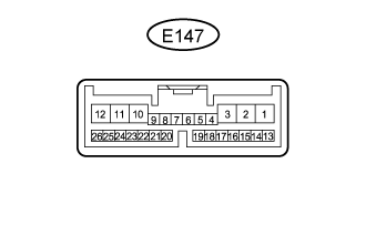 |
Disconnect the E147 windshield wiper relay connectors.
Measure the voltage and resistance according to the value(s) in the table below.
Terminal No. (Symbol) Wiring Color Terminal Description Condition Specified Condition E147-2 (IG) - Body ground B - Body ground IG power supply Engine switch on (IG) 11 to 14 V Engine switch off Below 1 V E147-8 (VR2) - E147-21 (VR1) W -R Adjust volume circit Windshield wiper switch adjusting ring changed 0 to 231 Ω E147-12 (E) - Body ground W-B - Body ground Body ground Always Below 1 Ω E147-16 (WIG) - Body ground B - Body ground IG power supply Engine switch on (IG) 11 to 14 V Engine switch off Below 1 V Reconnect the E147 windshield wiper relay connectors.
Measure the voltage according to the value(s) in the table below.
Terminal No. (Symbol) Wiring Color Terminal Description Condition Specified Condition E147-1 (+SM) - Body ground W - Body ground Front wiper motor operation signal Front wiper is operated 11 to 14 V Front wiper is stopped Below 1 V E147-3 (C1) - E147-5 (CO) L - R Windshield wiper assembly AUTO position signal Windshield wiper assembly in AUTO position Below 1 V Windshield wiper assembly in not AUTO position 11 to 14 V E147-10 (+1) - Body ground W - Body ground Front wiper motor low speed signal Front wiper motor in low operation 11 to 14 V Front wiper motor not operation 11 to 14 V E147-11 (+2) - Body ground R - Body ground Front wiper motor high speed signal Front wiper motor in high operation Below 1 V Front wiper motor not operation Below 1 V E147-14 (MPX1) - Body ground B - Body ground LIN communication signal Engine switch on (IG) Below 1 V E147-25 (W) - Body ground L - Body ground Front washer motor signal Front washer switch off 11 to 14 V Front washer switch on Below 1 V
| CHECK WINDSHIELD WIPER SWITCH |

Disconnect the E16 switch connector.
Measure the voltage and resistance according to the value(s) in the table below.
Terminal No. (Symbol) Wiring Color Terminal Description Condition Specified Condition E16-2 (+B) - E16-10 (E)*1 B - W-B Power source circuit (from battery) Engine switch off Below 1 V Engine switch on (IG) 11 to 14 V E16-3 (+B) - E16-5 (E)*2 B - W-B Power source circuit (from battery) Engine switch off Below 1 V Engine switch on (IG) 11 to 14 V E16-10 (E) - Body ground*1 W-B - Body ground Ground circuit Always Below 1 Ω E16-5 (E) - Body ground*2 W-B - Body ground Ground circuit Always Below 1 Ω - HINT:
- *1: for LH Side
- *2: for RH Side
| CHECK RAIN SENSOR |

Disconnect the R11 rain sensor connector.
Measure the voltage and resistance according to the value(s) in the table below.
Terminal No. (Symbol) Wiring Color Terminal Description Condition Specified Condition R11-4 (SIG) - Body ground G - Body ground IG signal circuit Engine switch off Below 1 V Engine switch on (IG) 11 to 14 V R11-1 (ES) - Body ground W - Body ground Ground circuit Always Below 1 Ω Reconnect the R11 rain sensor connector.
Measure the waveform according to the value(s) in the table below.
Terminal No. (Symbol) Wiring Color Terminal Description Condition Specified Condition R11-3 (MPX) - Body ground R - Body ground LIN communication signal Engine switch on (IG) Pulse generation
| NO. 2 MULTIPLEX NETWORK BODY ECU (w/ Washer Nozzle Heater System) |
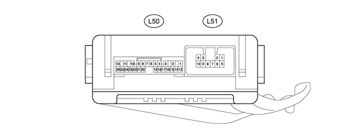
Disconnect the L50 and L51 No. 2 multiplex network body ECU connectors.
Measure the voltage and resistance according to the value(s) in the table below.
Terminal No. (Symbol) Wiring Color Terminal Description Condition Specified Condition L50-14 (BECU) - Body ground R - Body ground Power source circuit Always 11 to 14 V L50-13 (SIG) - Body ground G - Body ground IG signal circuit Engine switch off Below 1 V Engine switch on (IG) 11 to 14 V L50-7 (GND) - Body ground W-B - Body ground Ground circuit Always Below 1 Ω Reconnect the L50 and L51 No. 2 multiplex network body ECU connectors.
Measure the voltage according to the value(s) in the table below.
Terminal No. (Symbol) Wiring Color Terminal Description Condition Specified Condition L50-25 (WHTR) - Body ground GR - Body ground Washer nozzle heater signal circuit Engine switch on (IG), ambient temperature 6°C (42°F) or higher 11 to 14 V Engine switch on (IG), ambient temperature 5°C (41°F) or less Below 1 V