CHECK HARNESS AND CONNECTOR (AIR CONDITIONING AMPLIFIER ASSEMBLY - BATTERY AND BODY GROUND)
PERFORM ACTIVE TEST USING GTS (DAMPER SERVO MOTOR)
CHECK DAMPER SERVO MOTOR (CONNECTED TO AIR CONDITIONING HARNESS ASSEMBLY)
CHECK AIR CONDITIONING HARNESS ASSEMBLY
CHECK DAMPER SERVO MOTOR (CONNECTED TO NO. 2 AIR CONDITIONING HARNESS ASSEMBLY)
CHECK NO. 2 AIR CONDITIONING HARNESS ASSEMBLY
CHECK HARNESS AND CONNECTOR (AIR CONDITIONING AMPLIFIER ASSEMBLY AND BODY GROUND)
PERFORM ACTIVE TEST USING GTS (DAMPER SERVO MOTOR)
CHECK DAMPER SERVO MOTOR (CONNECTED TO AIR CONDITIONING HARNESS ASSEMBLY)
CHECK AIR CONDITIONING HARNESS ASSEMBLY
DTC B1497/97 BUS IC Communication Malfunction |
DESCRIPTION
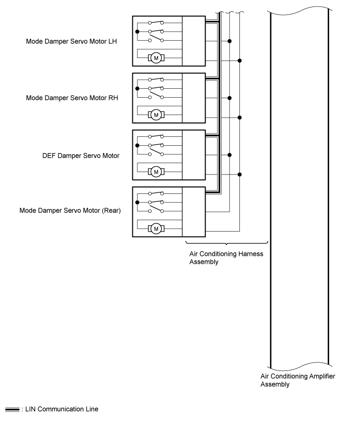
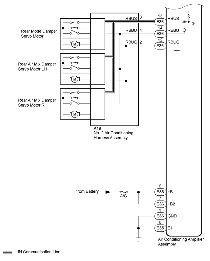
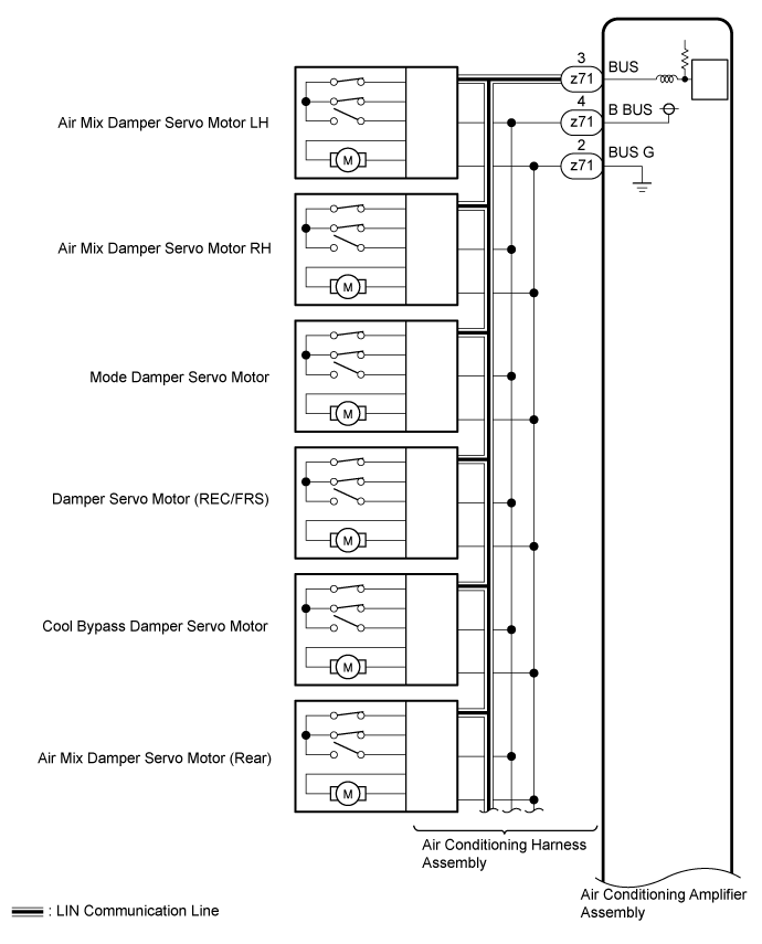
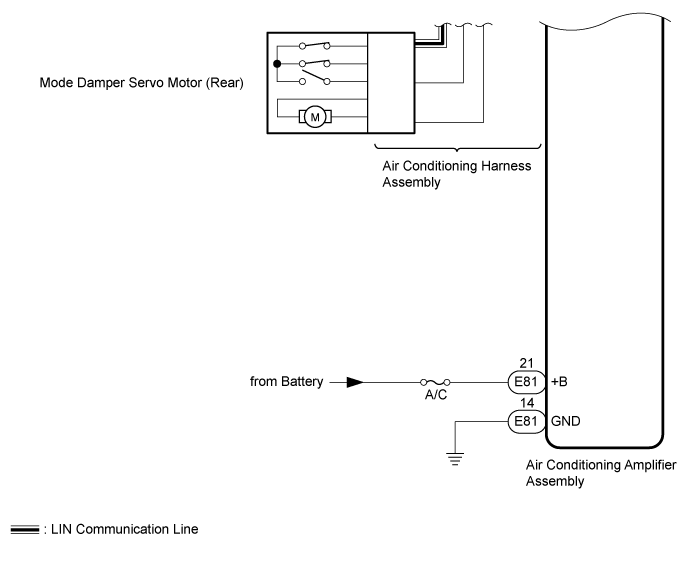
The air conditioning harness assembly connects the air conditioning amplifier assembly and each servo motor. The air conditioning amplifier assembly supplies power and sends operation instructions to each servo motor through the air conditioning harness assembly. Each servo motor sends the damper position information to the air conditioning amplifier assembly.| DTC Code | DTC Detection Condition | Trouble Area |
| B1497/97 | An open or error in the communication line. |
|
- *: w/ Rear Heater
WIRING DIAGRAM
| w/ Rear Heater: |

| w/o Rear Heater: |
INSPECTION PROCEDURE
- NOTICE:
- Inspect the fuses for circuits related to this system before performing the following inspection procedure.
| 1.CHECK FOR DTC |
Clear the DTCs (Click here).
Check for DTCs (Click here).
- OK:
- DTC B1497/97 is not output.
Result Result Proceed to OK A NG (w/ Rear Heater) B NG (w/o Rear Heater) C
|
| ||||
|
| ||||
| A | ||
| ||
| 2.CHECK HARNESS AND CONNECTOR (AIR CONDITIONING AMPLIFIER ASSEMBLY - BATTERY AND BODY GROUND) |
Disconnect the air conditioning amplifier assembly connector.
 |
Measure the resistance according to the value(s) in the table below.
- Standard Resistance:
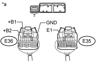
Tester Connection Condition Specified Condition E35-6 (E1) - Body ground Always Below 1 Ω E36-1 (GND) - Body ground Always Below 1 Ω
Measure the voltage according to the value(s) in the table below.
- Standard Voltage:
Tester Connection Condition Specified Condition E36-6 (+B1) - Body ground Always 11 to 14 V E36-7 (+B2) - Body ground Always 11 to 14 V
| *a | Front view of wire harness connector (to Air Conditioning Amplifier Assembly) |
|
| ||||
| OK | |
| 3.PERFORM ACTIVE TEST USING GTS (DAMPER SERVO MOTOR) |
Select the Active Test, use the GTS to generate a control command, and then check that the servo motors operates (Click here).
Air Conditioner Tester Display Test Part Control Range Diagnostic Note Air Mix Servo Targ Pulse(D) Air mix damper servo motor LH pulse Min.: 128, Max.: 383 Operates between 136 and 218 pulse Air Mix Servo Targ Pulse(P) Air mix damper servo motor RH pulse Min.: 128, Max.: 383 Operates between 136 and 218 pulse Air Outlet Servo Pulse (D) Mode damper servo motor LH Pulse Min.: 128, Max.: 383 Operates between 136 and 245 pulse Air Inlet Damper Targ Pulse Mode damper servo motor (REC/FRS) pulse Min.: 128, Max.: 383 Operates between 137 and 165 pulse Cool Air Bypass Pulse Cool bypass damper servo motor pulse Min.: 128, Max.: 383 Operates between 134 and 185 pulse Rear Air Mix Servo Targ Pulse Rear air mix damper servo motor LH*1 or RH*2 Pulse Min.: 128, Max.: 383 - Operates between 137 and 182 pulse (for LHD)
- Operates between 136 and 181 pulse (for RHD)
Air Outlet Servo Pulse (P) Mode damper servo motor RH*1 or LH*2 pulse Min.: 128, Max.: 383 - Operates between 134 and 245 pulse (for LHD)
- Operates between 136 and 248 pulse (for RHD)
A/M Servo Puls(F&R D) Air mix damper servo motor (rear LH*1 or RH*2) pulse Min.: 128, Max.: 383 - Operates between 141 and 169 pulse (for LHD)
- Operates between 133 and 161 pulse (for RHD)
A/M Servo Puls(F&R P) Air mix damper servo motor (rear RH*1 or LH*2) pulse Min.: 128, Max.: 383 - Operates between 133 and 161 pulse (for LHD)
- Operates between 141 and 169 pulse (for RHD)
A/O Servo Pulse(F&R D) Mode damper servo motor (rear) pulse Min.: 128, Max.: 383 Operates between 137 and 207 pulse A/O Servo Pulse(Rr D) Rear mode damper servo motor pulse Min.: 128, Max.: 383 Operates between 135 and 211 pulse DEF A/O Servo Pulse(D) DEF mode damper servo motor pulse Min.: 128, Max.: 383 Operates between 135 and 245 pulse Rear A/M Servo Pulse(P) Rear air mix damper servo motor RH pulse Min.: 128, Max.: 383 - Operates between 136 and 181 pulse (for LHD)
- Operates between 137 and 182 pulse (for RHD)
- *1: for LHD
- *2: for RHD
- OK:
- Arm of the damper servo motor selected in the Active Test moves smoothly.
Result Result Proceed to Any front damper servo motor is malfunctioning A All front damper servo motors are malfunctioning B Any rear damper servo motor is malfunctioning C All rear damper servo motors are malfunctioning D - Operates between 137 and 182 pulse (for LHD)
|
| ||||
|
| ||||
|
| ||||
| A | |
| 4.CHECK DAMPER SERVO MOTOR (CONNECTED TO AIR CONDITIONING HARNESS ASSEMBLY) |
Replace the malfunctioning damper servo motor connected to air conditioning harness assembly.
- for LHD: Click here
- for RHD: Click here
- HINT:
- Since the servo motor cannot be inspected while it is removed from the vehicle, replace the servo motor with a new one and check that the condition returns to normal.
- for LHD: Click here
Clear the DTCs (Click here).
Check for DTCs (Click here).
- OK:
- DTC B1497/97 is not output.
|
| ||||
| OK | ||
| ||
| 5.CHECK AIR CONDITIONING HARNESS ASSEMBLY |
Replace the air conditioning harness assembly with a new or known good one.
- for LHD: Click here
- for RHD: Click here
- for LHD: Click here
Clear the DTCs (Click here).
Check for DTCs (Click here).
- OK:
- DTC B1497/97 is not output.
|
| ||||
| OK | ||
| ||
| 6.CHECK HARNESS AND CONNECTOR (NO. 2 AIR CONDITIONING HARNESS ASSEMBLY - AIR CONDITIONING AMPLIFIER ASSEMBLY) |
Disconnect the K19 No. 2 air conditioning harness assembly connector.
Disconnect the E36 air conditioning amplifier assembly connector.
Measure the resistance according to the value(s) in the table below.
- Standard Resistance:
Tester Connection Condition Specified Condition K19-2 (RBUG) - E36-12 (RBUG) Always Below 1 Ω K19-3 (RBUS) - E36-13 (RBUS) Always Below 1 Ω K19-4 (RBBU) - E36-14 (RBBU) Always Below 1 Ω K19-2 (RBUG) or E36-12 (RBUG) - Body ground Always 10 kΩ or higher K19-3 (RBUS) or E36-13 (RBUS) - Body ground Always 10 kΩ or higher K19-4 (RBBU) or E36-14 (RBBU) - Body ground Always 10 kΩ or higher
|
| ||||
| OK | |
| 7.CHECK DAMPER SERVO MOTOR (CONNECTED TO NO. 2 AIR CONDITIONING HARNESS ASSEMBLY) |
Replace the malfunctioning damper servo motor connected to No. 2 air conditioning harness connector (Click here).
- HINT:
- Since the servo motor cannot be inspected while it is removed from the vehicle, replace the servo motor with a new one and check that the condition returns to normal.
Clear the DTCs (Click here).
Check for DTCs (Click here).
- OK:
- DTC B1497/97 is not output.
|
| ||||
| OK | ||
| ||
| 8.CHECK NO. 2 AIR CONDITIONING HARNESS ASSEMBLY |
Replace the No. 2 air conditioning harness assembly with a new or known good one (Click here).
Clear the DTCs (Click here).
Check for DTCs (Click here).
- OK:
- DTC B1497/97 is not output.
|
| ||||
| OK | ||
| ||
| 9.CHECK HARNESS AND CONNECTOR (AIR CONDITIONING AMPLIFIER ASSEMBLY AND BODY GROUND) |
Disconnect the air conditioning amplifier assembly connector.
 |
Measure the resistance according to the value(s) in the table below.
- Standard Resistance:
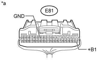
Tester Connection Condition Specified Condition E81-14 (GND) - Body ground Always Below 1 Ω
Measure the voltage according to the value(s) in the table below.
- Standard Voltage:
Tester Connection Condition Specified Condition E81-21 (+B1) - Body ground Always 11 to 14 V
| *a | Front view of wire harness connector (to Air Conditioning Amplifier Assembly) |
|
| ||||
| OK | |
| 10.PERFORM ACTIVE TEST USING GTS (DAMPER SERVO MOTOR) |
Select the Active Test, use the GTS to generate a control command, and then check that the servo motors operates (Click here).
Air Conditioner Tester Display Test Part Control Range Diagnostic Note Air Mix Servo Targ Pulse(D) Air mix damper servo motor LH pulse Min.: 128, Max.: 383 Operates between 136 and 218 pulse Air Mix Servo Targ Pulse(P) Air mix damper servo motor RH pulse Min.: 128, Max.: 383 Operates between 136 and 218 pulse Air Outlet Servo Pulse (D) Mode damper servo motor Pulse Min.: 128, Max.: 383 Operates between 136 and 245 pulse Air Inlet Damper Targ Pulse Mode damper servo motor (REC/FRS) pulse Min.: 128, Max.: 383 Operates between 137 and 165 pulse Cool Air Bypass Pulse Cool bypass damper servo motor pulse Min.: 128, Max.: 383 Operates between 134 and 185 pulse Air Outlet Servo Pulse (P) Mode damper servo motor RH*1 or LH*2 pulse Min.: 128, Max.: 383 - Operates between 134 and 245 pulse (for LHD)
- Operates between 136 and 248 pulse (for RHD)
A/O Servo Pulse(F&R D) Mode damper servo motor (rear) pulse Min.: 128, Max.: 383 Operates between 137 and 207 pulse - OK:
- Arm of the damper servo motor selected in the Active Test moves smoothly.
Result Result Proceed to Any front damper servo motor is malfunctioning A All front damper servo motors are malfunctioning B - Operates between 134 and 245 pulse (for LHD)
|
| ||||
| A | |
| 11.CHECK DAMPER SERVO MOTOR (CONNECTED TO AIR CONDITIONING HARNESS ASSEMBLY) |
Replace the malfunctioning damper servo motor connected to air conditioning harness assembly.
- for LHD: Click here
- for RHD: Click here
- HINT:
- Since the servo motor cannot be inspected while it is removed from the vehicle, replace the servo motor with a new one and check that the condition returns to normal.
- for LHD: Click here
Clear the DTCs (Click here).
Check for DTCs (Click here).
- OK:
- DTC B1497/97 is not output.
|
| ||||
| OK | ||
| ||
| 12.CHECK AIR CONDITIONING HARNESS ASSEMBLY |
Replace the air conditioning harness assembly with a new or known good one.
- for LHD: Click here
- for RHD: Click here
- for LHD: Click here
Clear the DTCs (Click here).
Check for DTCs (Click here).
- OK:
- DTC B1497/97 is not output.
|
| ||||
| OK | ||
| ||