DESCRIPTION
WIRING DIAGRAM
INSPECTION PROCEDURE
PERFORM ACTIVE TEST USING GTS (INTERIOR ILLUMINATION LIGHT1)
CHECK HARNESS AND CONNECTOR (MAIN BODY ECU - FRONT DOOR TRIM BOARD SUB-ASSEMBLY LH)
INSPECT FRONT DOOR TRIM BOARD SUB-ASSEMBLY LH
CHECK HARNESS AND CONNECTOR (MAIN BODY ECU - FRONT DOOR TRIM BOARD SUB-ASSEMBLY RH)
INSPECT FRONT DOOR TRIM BOARD SUB-ASSEMBLY RH
CHECK HARNESS AND CONNECTOR (MAIN BODY ECU - REAR DOOR TRIM BOARD SUB-ASSEMBLY LH)
INSPECT REAR DOOR TRIM BOARD SUB-ASSEMBLY LH
CHECK HARNESS AND CONNECTOR (MAIN BODY ECU - REAR DOOR TRIM BOARD SUB-ASSEMBLY RH)
INSPECT REAR DOOR TRIM BOARD SUB-ASSEMBLY RH
LIGHTING SYSTEM - Door Illumination Circuit |
DESCRIPTION
The rear door illumination is controlled by the main body ECU.
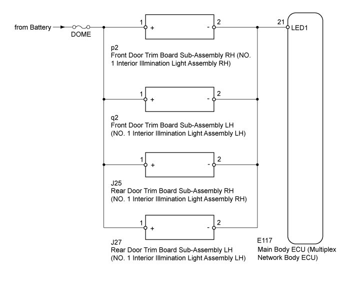
WIRING DIAGRAM
INSPECTION PROCEDURE
- NOTICE:
- Inspect the fuses for circuits related to this system before performing the following inspection procedure.
- If the main body ECU (multiplex network body ECU) is replaced, refer to the Service Bulletin.
| 1.PERFORM ACTIVE TEST USING GTS (INTERIOR ILLUMINATION LIGHT1) |
Operate the GTS according to the steps on the display and select "Active Test".
Main BodyTester Display
| Test Part
| Control Range
| Diagnostic Note
|
Interior Illumination Light1
| door illumination light*
| OFF or ON
| -
|
*: 15 seconds after turning the engine switch off, check the operation once the rear door illumination turns off.
- OK:
- Rear door illumination illuminates.
ResultResult
| Proceed
|
OK
| A
|
NG (Front Door LH Side)
| B
|
NG (Front Door RH Side)
| C
|
NG (Rear Door LH Side)
| D
|
NG (Rear Door RH Side)
| E
|
| A |
|
|
|
| PROCEED TO NEXT SUSPECTED AREA SHOWN IN PROBLEM SYMPTOMS TABLE (Click here) |
|
| 2.CHECK HARNESS AND CONNECTOR (MAIN BODY ECU - FRONT DOOR TRIM BOARD SUB-ASSEMBLY LH) |
Remove the front door trim board sub-assembly LH.
Remove the DOME fuse from cowl side junction block LH.
Remove the main body ECU (multiplex network body ECU) from the junction block assembly LH.
Measure the resistance according to the value(s) in the table below.
- Standard Resistance:
Tester Connection
| Condition
| Specified Condition
|
E117-21 (LED1) - q2-2 (-)
| Always
| Below 1 Ω
|
2 (DOME fuse holder) - q2-1 (+)
| Always
| Below 1 Ω
|
E117-21 (LED1) - Body ground
| Always
| 10 kΩ or higher
|
2 (DOME fuse holder) or q2-1 (+) - Body ground
| Always
| 10 kΩ or higher
|
| | REPAIR OR REPLACE HARNESS OR CONNECTOR |
|
|
| 3.INSPECT FRONT DOOR TRIM BOARD SUB-ASSEMBLY LH |
Temporarily replace the eront door trim board sub-assembly LH with a new or normally functioning one.
- OK:
- The illumination illuminates normally.
| | REPLACE MAIN BODY ECU (MULTIPLEX NETWORK BODY ECU) |
|
|
| OK |
|
|
|
| END (FRONT DOOR TRIM BOARD SUB-ASSEMBLY LH IS DEFECTIVE) |
|
| 4.CHECK HARNESS AND CONNECTOR (MAIN BODY ECU - FRONT DOOR TRIM BOARD SUB-ASSEMBLY RH) |
Remove the front door trim board sub-assembly RH.
Remove the DOME fuse from cowl side junction block LH.
Remove the main body ECU (multiplex network body ECU) from the junction block assembly LH.
Measure the resistance according to the value(s) in the table below.
- Standard Resistance:
Tester Connection
| Condition
| Specified Condition
|
E117-21 (LED1) - p2-2 (-)
| Always
| Below 1 Ω
|
2 (DOME fuse holder) - p2-1 (+)
| Always
| Below 1 Ω
|
E117-21 (LED1) - Body ground
| Always
| 10 kΩ or higher
|
2 (DOME fuse holder) or p2-1 (+) - Body ground
| Always
| 10 kΩ or higher
|
| | REPAIR OR REPLACE HARNESS OR CONNECTOR |
|
|
| 5.INSPECT FRONT DOOR TRIM BOARD SUB-ASSEMBLY RH |
Temporarily replace the front door trim board sub-assembly RH with a new or normally functioning one.
- OK:
- The illumination illuminates normally.
| | REPLACE MAIN BODY ECU (MULTIPLEX NETWORK BODY ECU) |
|
|
| OK |
|
|
|
| END (FRONT DOOR TRIM BOARD SUB-ASSEMBLY RH IS DEFECTIVE) |
|
| 6.CHECK HARNESS AND CONNECTOR (MAIN BODY ECU - REAR DOOR TRIM BOARD SUB-ASSEMBLY LH) |
Remove the rear door trim board sub-assembly LH.
Remove the DOME fuse from cowl side junction block LH.
Remove the main body ECU (multiplex network body ECU) from the junction block assembly LH.
Measure the resistance according to the value(s) in the table below.
- Standard Resistance:
Tester Connection
| Condition
| Specified Condition
|
E117-21 (LED1) - J27-2 (-)
| Always
| Below 1 Ω
|
2 (DOME fuse holder) - J27-1 (+)
| Always
| Below 1 Ω
|
E117-21 (LED1) - Body ground
| Always
| 10 kΩ or higher
|
2 (DOME fuse holder) or J27-1 (+) - Body ground
| Always
| 10 kΩ or higher
|
| | REPAIR OR REPLACE HARNESS OR CONNECTOR |
|
|
| 7.INSPECT REAR DOOR TRIM BOARD SUB-ASSEMBLY LH |
Temporarily replace the rear door trim board sub-assembly LH with a new or normally functioning one.
- OK:
- The illumination illuminates normally.
| | REPLACE MAIN BODY ECU (MULTIPLEX NETWORK BODY ECU) |
|
|
| OK |
|
|
|
| END (REAR DOOR TRIM BOARD SUB-ASSEMBLY LH IS DEFECTIVE) |
|
| 8.CHECK HARNESS AND CONNECTOR (MAIN BODY ECU - REAR DOOR TRIM BOARD SUB-ASSEMBLY RH) |
Remove the rear door trim board sub-assembly RH.
Remove the DOME fuse from cowl side junction block LH.
Remove the main body ECU (multiplex network body ECU) from the junction block assembly LH.
Measure the resistance according to the value(s) in the table below.
- Standard Resistance:
Tester Connection
| Condition
| Specified Condition
|
E117-21 (LED1) - J25-2 (-)
| Always
| Below 1 Ω
|
2 (DOME fuse holder) - J25-1 (+)
| Always
| Below 1 Ω
|
E117-21 (LED1) - Body ground
| Always
| 10 kΩ or higher
|
2 (DOME fuse holder) or J25-1 (+) - Body ground
| Always
| 10 kΩ or higher
|
| | REPAIR OR REPLACE HARNESS OR CONNECTOR |
|
|
| 9.INSPECT REAR DOOR TRIM BOARD SUB-ASSEMBLY RH |
Temporarily replace the rear door trim board sub-assembly RH with a new or normally functioning one.
- OK:
- The illumination illuminates normally.
| | REPLACE MAIN BODY ECU (MULTIPLEX NETWORK BODY ECU) |
|
|
| OK |
|
|
|
| END (REAR DOOR TRIM BOARD SUB-ASSEMBLY RH IS DEFECTIVE) |
|