Dtc C1Abd Short To +B In Buzzer
DESCRIPTION
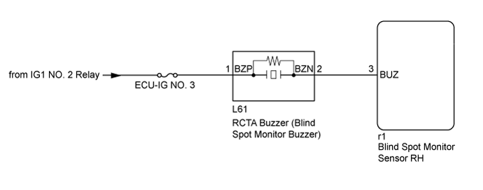
WIRING DIAGRAM
INSPECTION PROCEDURE
CHECK FOR DTC
CHECK HARNESS AND CONNECTOR (RCTA BUZZER - BATTERY AND BLIND SPOT MONITOR SENSOR RH)
REPLACE RCTA BUZZER (BLIND SPOT MONITOR BUZZER)
CHECK FOR DTC
DTC C1ABD Short to +B in Buzzer |
DTC C1ABE Short to GND or Open in Buzzer |
DESCRIPTION
- DTC C1ABD is stored when the blind spot monitor sensor RH detects a +B short in RCTA buzzer (blind spot monitor buzzer) circuit.
- DTC C1ABE is stored when the blind spot monitor sensor RH detects a ground short or open in RCTA buzzer (blind spot monitor buzzer) circuit.
DTC No.
| DTC Detection Condition
| Trouble Area
|
C1ABD
| Both of the following conditions are met:
- The blind spot monitor main switch (steering pad switch assembly [multi-function switch]) is on with the engine switch on (IG).
- The blind spot monitor sensor is not sending voltage to the buzzer but the buzzer receives voltage above a specified level for a specified period of time.
| - Blind spot monitor sensor RH
- RCTA buzzer (blind spot monitor buzzer)
- Harness or connector
|
C1ABE
| Both of the following conditions are met:
- The blind spot monitor main switch (steering pad switch assembly [multi-function switch]) is on with the engine switch on (IG).
- The current flowing to the buzzer is below a specified value when buzzer operation voltage is being sent to the buzzer.
| - Blind spot monitor sensor RH
- RCTA buzzer (blind spot monitor buzzer)
- Harness or connector
|
WIRING DIAGRAM
INSPECTION PROCEDURE
- NOTICE:
- When checking for DTCs, make sure that the blind spot main switch (steering pad switch assembly [multi-function switch]) is on.
- Inspect the fuses for circuits related to this system before performing the following inspection procedure.
Clear the DTCs (Click here).
Recheck for DTCs and check if the same DTC is output again.
- OK:
- No DTCs are output.
| 2.CHECK HARNESS AND CONNECTOR (RCTA BUZZER - BATTERY AND BLIND SPOT MONITOR SENSOR RH) |
Disconnect the L61 RCTA buzzer (blind spot monitor buzzer) connector.
Disconnect the r1 blind spot monitor sensor RH connector.
Measure the resistance according to the value(s) in the table below.
- Standard Resistance:
Tester Connection
| Condition
| Specified Condition
|
L61-2 (BZN) - r1-3 (BUZ)
| Always
| Below 1 Ω
|
L61-2 (BZN) - Body ground
| Always
| 10 kΩ or higher
|
Measure the voltage according to the value(s) in the table below.
- Standard Voltage:
Tester Connection
| Switch Condition
| Specified Condition
|
L61-1 (BZP) - Body ground
| Engine switch on (IG)
| 11 to 14 V
|
L61-1 (BZP) - Body ground
| Engine switch off
| Below 1 V
|
| | REPAIR OR REPLACE HARNESS OR CONNECTOR |
|
|
| 3.REPLACE RCTA BUZZER (BLIND SPOT MONITOR BUZZER) |
Replace the RCTA buzzer (blind spot monitor buzzer) (Click here).
Clear the DTCs (Click here).
Recheck for DTCs and check if the same DTC is output again.
- OK:
- No DTCs are output.
| OK |
|
|
|
| END (RCTA BUZZER [BLIND SPOT MONITOR BUZZER] WAS DEFECTIVE) |
|