Power Window Control System (For Models With Jam Protection Function On 4 Windows) -- Terminals Of Ecu |
| CHECK FRONT POWER WINDOW REGULATOR MOTOR ASSEMBLY LH |

Disconnect the I12 motor connector.
Measure the resistance and voltage according to the value(s) in the table below.
If the result is not as specified, there may be a malfunction on the wire harness side.Terminal No. (Symbol) Wiring Color Terminal Description Condition Specified Condition I12-2 (B) - I12-1 (GND) L - W-B Battery power supply Always 11 to 14 V I12-1 (GND) - Body ground W-B - Body ground Ground Always Below 1 Ω Reconnect the I12 motor connector.
Measure the voltage according to the value(s) in the table below.
If the result is not as specified, the motor may be malfunctioning.Terminal No. (Symbol) Wiring Color Terminal Description Condition Specified Condition I12-10 (UP) - I12-1 (GND) L - W-B Power window up operation Ignition switch ON, multiplex network master switch off → up 11 to 14 V → Below 1 V I12-10 (UP) - I12-1 (GND) L - W-B Power window up operation Ignition switch ON, door glass fully open → power window auto up operation → door glass fully closed 11 to 14 V → Below 1 V → 11 to 14 V I12-7 (DOWN) - I12-1 (GND) B - W-B Power window down operation Ignition switch ON, multiplex network master switch off → down 11 to 14 V → Below 1 V I12-7 (DOWN) - I12-1 (GND) B - W-B Power window down operation Ignition switch ON, door glass fully closed → power window auto down operation → door glass fully open 11 to 14 V → Below 1 V → 11 to 14 V
| CHECK FRONT POWER WINDOW REGULATOR MOTOR RH |

Disconnect the I4 motor connector.
Measure the resistance and voltage according to the value(s) in the table below.
If the result is not as specified, there may be a malfunction on the wire harness side.Terminal No. (Symbol) Wiring Color Terminal Description Condition Specified Condition I4-2 (B) - I4-1 (GND) L - W-B Battery power supply Always 11 to 14 V I4-1 (GND) - Body ground W-B - Body ground Ground Always Below 1 Ω Reconnect the I4 motor connector.
Measure the voltage according to the value(s) in the table below.
If the result is not as specified, the motor may be malfunctioning.Terminal No. (Symbol) Wiring Color Terminal Description Condition Specified Condition I4-10 (UP) - I4-1 (GND) L - W-B Power window up operation Ignition switch ON, power window regulator switch off → up 11 to 14 V → Below 1 V I4-10 (UP) - I4-1 (GND) L - W-B Power window up operation Ignition switch ON, door glass fully open → power window auto up operation → door glass fully closed 11 to 14 V → Below 1 V → 11 to 14 V I4-7 (DOWN) - I4-1 (GND) B - W-B Power window down operation Ignition switch ON, power window regulator switch off → down 11 to 14 V → Below 1 V I4-7 (DOWN) - I4-1 (GND) B - W-B Power window down operation Ignition switch ON, door glass fully closed → power window auto down operation → door glass fully open 11 to 14 V → Below 1 V → 11 to 14 V
| CHECK REAR POWER WINDOW REGULATOR MOTOR LH |

Disconnect the J11 motor connector.
Measure the resistance and voltage according to the value(s) in the table below.
If the result is not as specified, there may be a malfunction on the wire harness side.Terminal No. (Symbol) Wiring Color Terminal Description Condition Specified Condition J11-2 (B) - J11-1 (GND) L - W-B Battery power supply Always 11 to 14 V J11-1 (GND) - Body ground W-B - Body ground Ground Always Below 1 Ω Reconnect the J11 motor connector.
Measure the voltage according to the value(s) in the table below.
If the result is not as specified, the motor may be malfunctioning.Terminal No. (Symbol) Wiring Color Terminal Description Condition Specified Condition J11-10 (UP) - J11-1 (GND) L - W-B Power window up operation Ignition switch ON, power window regulator switch off → up 11 to 14 V → Below 1 V J11-10 (UP) - J11-1 (GND) L - W-B Power window up operation Ignition switch ON, door glass fully open → power window auto up operation → door glass fully closed 11 to 14 V → Below 1 V → 11 to 14 V J11-7 (DOWN) - J11-1 (GND) Y - B Power window down operation Ignition switch ON, power window regulator switch off → down 11 to 14 V → Below 1 V J11-7 (DOWN) - J11-1 (GND) Y - B Power window down operation Ignition switch ON, door glass fully closed → power window auto down operation → door glass fully open 11 to 14 V → Below 1 V → 11 to 14 V
| CHECK REAR POWER WINDOW REGULATOR MOTOR RH |

Disconnect the J4 motor connector.
Measure the resistance and voltage according to the value(s) in the table below.
If the result is not as specified, there may be a malfunction on the wire harness side.Terminal No. (Symbol) Wiring Color Terminal Description Condition Specified Condition J4-2 (B) - J4-1 (GND) L - W-B Battery power supply Always 11 to 14 V J4-1 (GND) - Body ground W-B - Body ground Ground Always Below 1 Ω Reconnect the J4 motor connector.
Measure the voltage according to the value(s) in the table below.
If the result is not as specified, the motor may be malfunctioning.Terminal No. (Symbol) Wiring Color Terminal Description Condition Specified Condition J4-10 (UP) - J4-1 (GND) L - W-B Power window up operation Ignition switch ON, power window regulator switch off → up 11 to 14 V → Below 1 V J4-10 (UP) - J4-1 (GND) L - W-B Power window up operation Ignition switch ON, door glass fully open → power window auto up operation → door glass fully closed 11 to 14 V → Below 1 V → 11 to 14 V J4-7 (DOWN) - J4-1 (GND) B - W-B Power window down operation Ignition switch ON, power window regulator switch off → down 11 to 14 V → Below 1 V J4-7 (DOWN) - J4-1 (GND) B - W-B Power window down operation Ignition switch ON, door glass fully closed → power window auto down operation → door glass fully open 11 to 14 V → Below 1 V → 11 to 14 V
| CHECK MULTIPLEX NETWORK MASTER SWITCH |

Disconnect the I11*1 or I22*2 master switch connector.
- HINT:
- *1: for LHD
- *2: for RHD
Measure the resistance and voltage according to the value(s) in the table below.
for LHD Terminal No. (Symbol) Wiring Color Terminal Description Condition Specified Condition I11-11 (B) - I11-12 (GND) L - W-B Battery power supply Always 11 to 14 V I11-12 (GND) - Body ground W-B - Body ground Ground Always Below 1 Ω
If the result is not as specified, there may be a malfunction on the wire harness side.for RHD Terminal No. (Symbol) Wiring Color Terminal Description Condition Specified Condition I22-11 (B) - I22-12 (GND) L - W-B Battery power supply Always 11 to 14 V I22-12 (GND) - Body ground W-B - Body ground Ground Always Below 1 Ω Reconnect the I11*1 or I22*2 master switch connector.
- HINT:
- *1: for LHD
- *2: for RHD
Measure the voltage according to the value(s) in the table below.
for LHD Terminal No. (Symbol) Wiring Color Terminal Description Condition Specified Condition I11-20 (UP) - I11-12 (GND) L - W-B Power window up operation Ignition switch ON, multiplex network master switch off → up 11 to 14 V → Below 1 V I11-20 (UP) - I11-12 (GND) L - W-B Power window up operation Ignition switch ON, door glass fully open → power window auto up operation → door glass fully closed 11 to 14 V → Below 1 V → 11 to 14 V I11-15 (DOWN) - I11-12 (GND) B - W-B Power window down operation Ignition switch ON, multiplex network master switch off → down 11 to 14 V → Below 1 V I11-15 (DOWN) - I11-12 (GND) B - W-B Power window down operation Ignition switch ON, door glass fully closed → power window auto down operation → door glass fully open 11 to 14 V → Below 1 V → 11 to 14 V
If the result is not as specified, the master switch may be malfunctioning.for RHD Terminal No. (Symbol) Wiring Color Terminal Description Condition Specified Condition I22-20 (UP) - I22-12 (GND) L - W-B Power window up operation Ignition switch ON, multiplex network master switch off → up 11 to 14 V → Below 1 V I22-20 (UP) - I22-12 (GND) L - W-B Power window up operation Ignition switch ON, door glass fully open → power window auto up operation → door glass fully closed 11 to 14 V → Below 1 V → 11 to 14 V I22-15 (DOWN) - I22-12 (GND) B - W-B Power window down operation Ignition switch ON, multiplex network master switch off → down 11 to 14 V → Below 1 V I22-15 (DOWN) - I22-12 (GND) B - W-B Power window down operation Ignition switch ON, door glass fully closed → power window auto down operation → door glass fully open 11 to 14 V → Below 1 V → 11 to 14 V
| CHECK FRONT PASSENGER SIDE POWER WINDOW REGULATOR SWITCH |

Disconnect the I3*1 or I25*2 switch connector.
- HINT:
- *1: for LHD
- *2: for RHD
Measure the resistance according to the value(s) in the table below.
for LHD Terminal No. (Symbol) Wiring Color Terminal Description Condition Specified Condition I3-1 (GND) - Body ground W-B - Body ground Ground Always Below 1 Ω
If the result is not as specified, there may be a malfunction on the wire harness side.for RHD Terminal No. (Symbol) Wiring Color Terminal Description Condition Specified Condition I25-1 (GND) - Body ground W-B - Body ground Ground Always Below 1 Ω Reconnect the I3*1 or I25*2 switch connector.
- HINT:
- *1: for LHD
- *2: for RHD
Measure the voltage according to the value(s) in the table below.
for LHD Terminal No. (Symbol) Wiring Color Terminal Description Condition Specified Condition I3-6 (UP) - I3-1 (GND) L - W-B Power window up operation Ignition switch ON, power window regulator switch off → up 11 to 14 V → Below 1 V I3-7 (DOWN) - I3-1 (GND) B - W-B Power window down operation Ignition switch ON, power window regulator switch off → down 11 to 14 V → Below 1 V I3-8 (AUTO) - I3-1 (GND) R - W-B Power window up operation Ignition switch ONand door glass fully open → power window auto up operation → door glass fully closed 11 to 14 V → Below 1 V → 11 to 14 V I3-8 (AUTO) - I3-1 (GND) R - W-B Power window down operation Ignition switch ON, door glass fully closed → power window auto down operation → door glass fully open 11 to 14 V → Below 1 V → 11 to 14 V
If the result is not as specified, the switch may be malfunctioning.for RHD Terminal No. (Symbol) Wiring Color Terminal Description Condition Specified Condition I25-6 (UP) - I25-1 (GND) L - W-B Power window up operation Ignition switch ON, power window regulator switch off → up 11 to 14 V → Below 1 V I25-7 (DOWN) - I25-1 (GND) B - W-B Power window down operation Ignition switch ON, power window regulator switch off → down 11 to 14 V → Below 1 V I25-8 (AUTO) - I25-1 (GND) R - W-B Power window up operation Ignition switch ONand door glass fully open → power window auto up operation → door glass fully closed 11 to 14 V → Below 1 V → 11 to 14 V I25-8 (AUTO) - I25-1 (GND) R - W-B Power window down operation Ignition switch ON, door glass fully closed → power window auto down operation → door glass fully open 11 to 14 V → Below 1 V → 11 to 14 V
| CHECK REAR POWER WINDOW REGULATOR SWITCH LH |
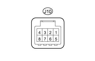
Disconnect the J10 switch connector.
Measure the resistance according to the value(s) in the table below.
If the result is not as specified, there may be a malfunction on the wire harness side.Terminal No. (Symbol) Wiring Color Terminal Description Condition Specified Condition J10-1 (GND) - Body ground W-B - Body ground Ground Always Below 1 Ω Reconnect the J10 switch connector.
Measure the voltage according to the value(s) in the table below.
If the result is not as specified, the switch may be malfunctioning.Terminal No. (Symbol) Wiring Color Terminal Description Condition Specified Condition J10-6 (UP) - J10-1 (GND) L - W-B Power window up operation Ignition switch ON, power window regulator switch off → up 11 to 14 V → Below 1 V J10-7 (DOWN) - J10-1 (GND) B - W-B Power window down operation Ignition switch ON, power window regulator switch off → down 11 to 14 V → Below 1 V J10-8 (AUTO) - J10-1 (GND) R - W-B Power window up operation Ignition switch ON, door glass fully open → power window auto up operation → door glass fully closed 11 to 14 V → Below 1 V → 11 to 14 V J10-8 (AUTO) - J10-1 (GND) R - W-B Power window down operation Ignition switch ON, door glass fully closed → power window auto down operation → door glass fully open 11 to 14 V → Below 1 V → 11 to 14 V
| CHECK REAR POWER WINDOW REGULATOR SWITCH RH |
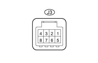
Disconnect the J3 switch connector.
Measure the resistance according to the value(s) in the table below.
If the result is not as specified, there may be a malfunction on the wire harness side.Terminal No. (Symbol) Wiring Color Terminal Description Condition Specified Condition J3-1 (GND) - Body ground W-B - Body ground Ground Always Below 1 Ω Reconnect the J3 switch connector.
Measure the voltage according to the value(s) in the table below.
If the result is not as specified, the switch may be malfunctioning.Terminal No. (Symbol) Wiring Color Terminal Description Condition Specified Condition J3-6 (UP) - J3-1 (GND) L - W-B Power window up operation Ignition switch ON, power window regulator switch off → up 11 to 14 V → Below 1 V J3-7 (DOWN) - J3-1 (GND) B - W-B Power window down operation Ignition switch ON, power window regulator switch off → down 11 to 14 V → Below 1 V J3-8 (AUTO) - J3-1 (GND) R - W-B Power window up operation Ignition switch ON, door glass fully open → power window auto up operation → door glass fully closed 11 to 14 V → Below 1 V → 11 to 14 V J3-8 (AUTO) - J3-1 (GND) R - W-B Power window down operation Ignition switch ON, door glass fully closed → power window auto down operation → door glass fully open 11 to 14 V → Below 1 V → 11 to 14 V
| CHECK MAIN BODY ECU (COWL SIDE JUNCTION BLOCK LH) |
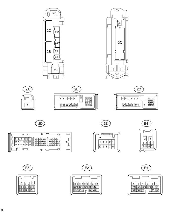
Disconnect the 2A, 2C, E1, E2 and E3 ECU connectors.
Measure the resistance and voltage according to value(s) in the table below.
Terminal No. (Symbol) Wiring Color Terminal Description Condition Specified Condition E3-1 (GND3) - 2A-62 (GND2) BR - W-B Ground Always Below 1 Ω 2D-62 (GND2) - Body ground W-B - Body ground Ground Always Below 1 Ω 2A-1 (IG) - Body ground B - Body ground IG power supply Always 11 to 14 V E2-1 (AM2) - Body ground W - Body ground Battery power supply Always 11 to 14 V E1-6 (AM1) - Body ground W - Body ground Battery power supply Always 11 to 14 V E1-24 (DCTY) - Body ground L - Body ground*1, *3
Y - Body ground*2, *4Driver side door courtesy light switch input Driver side door open Below 1 Ω Driver side door closed 10 kΩ or higher E2-21 (PCTY) - Body ground Y - Body ground*1, *3
P - Body ground*1, *4
L - Body ground*2Front passenger side door courtesy light switch input Front passenger side door open Below 1 Ω Front passenger side door closed 10 kΩ or higher E2-7 (RCTY) - Body ground G - Body ground Rear RH side door courtesy light switch input Rear RH side door open Below 1 Ω Rear RH side door closed 10 kΩ or higher 2C-2 (LCTY) - Body ground W - Body ground Rear LH side door courtesy light switch input Rear LH side door open Below 1 Ω Rear LH side door closed 10 kΩ or higher - HINT:
- *1: for LHD
- *2: for RHD
- *3: Model code: GRJ200L-GNANKC, URJ202L-GNTEKC
- *4: Model code except: GRJ200L-GNANKC, URJ202L-GNTEKC
- If the result is not as specified, the wire harness side may have a malfunction.