Skid Control Buzzer -- Removal |
- HINT:
- Other than areas where instructions are provided, use the same procedures for the RH and LH sides.
- The procedure listed below is for the LH side.
| 1. PRECAUTION |
- NOTICE:
- After turning the ignition switch off, waiting time may be required before disconnecting the cable from the battery terminal. Therefore, make sure to read the disconnecting the cable from the battery terminal notice before proceeding with work (Click here).
| 2. DISCONNECT CABLE FROM NEGATIVE BATTERY TERMINAL |
- NOTICE:
- When disconnecting the cable, some systems need to be initialized after the cable is reconnected (Click here).
| 3. REMOVE FRONT DOOR SCUFF PLATE |
 |
Detach the 7 claws and 4 clips, and remove the front door scuff plate LH.
| 4. REMOVE NO. 1 INSTRUMENT PANEL UNDER COVER SUB-ASSEMBLY |
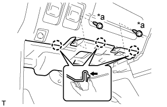 |
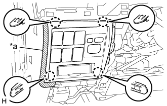
Remove the 2 screws <A>.
Text in Illustration *a Screw <A>
Detach the 3 claws.
Disconnect the connector and remove the No. 1 instrument panel under cover sub-assembly.
| 5. REMOVE COWL SIDE TRIM BOARD |
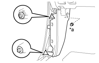 |
Remove the cap nut.
Text in Illustration *a Cap Nut
Detach the 2 clips and remove the cowl side trim board LH.
| 6. REMOVE LOWER NO. 1 INSTRUMENT PANEL FINISH PANEL |
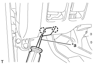 |
Using a screwdriver, detach the 2 claws and open the hole cover.
- HINT:
- Tape the screwdriver tip before use.
Text in Illustration *a Protective Tape
Put protective tape around the lower No. 1 instrument panel finish panel.
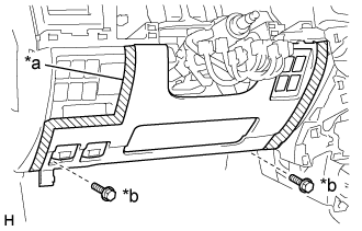 |
Remove the 2 bolts <B>.
Text in Illustration *a Protective Tape *b Bolt <B>
w/ Driver Side Knee Airbag:
Detach the 16 claws.
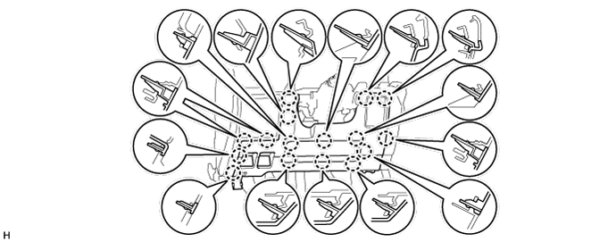
w/o Driver Side Knee Airbag:
Detach the 9 claws.
for Automatic Air Conditioning System:
Detach the 2 claws and remove the room temperature sensor.

Detach the 2 claws and disconnect the 2 control cables.
 |
Disconnect the connectors and remove the lower No. 1 instrument panel finish panel.
| 7. REMOVE NO. 1 SWITCH HOLE BASE |
 |
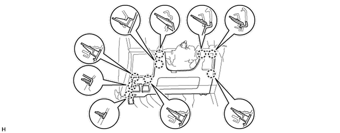
Put protective tape around the No. 1 switch hole base.
Text in Illustration *a Protective Tape
Detach the 4 claws.
Disconnect the connectors and remove the No. 1 switch hole base.
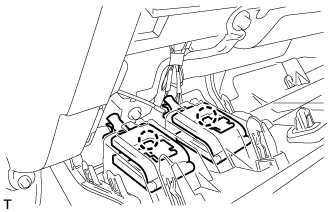
| 8. REMOVE SKID CONTROL BUZZER ASSEMBLY (for LHD) |
Detach the clamp and remove the buzzer.
 |
Disconnect the buzzer connector.
| 9. REMOVE SKID CONTROL BUZZER ASSEMBLY (for RHD) |
Detach the clamp and remove the buzzer.
 |
Disconnect the buzzer connector.