Lighting System Vehicle Speed Signal Circuit
DESCRIPTION
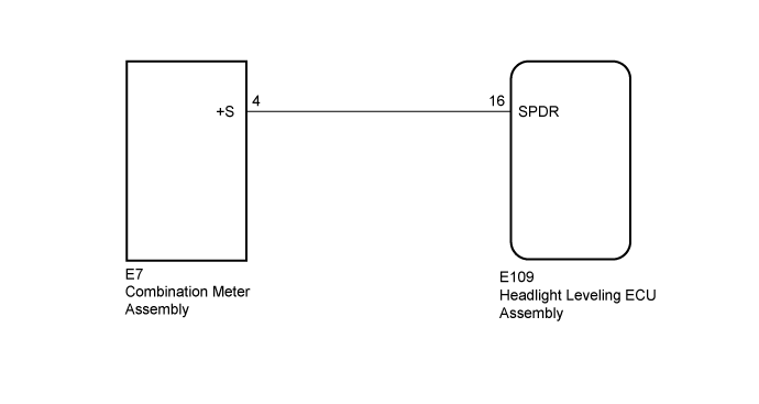
WIRING DIAGRAM
INSPECTION PROCEDURE
READ VALUE USING INTELLIGENT TESTER (VEHICLE SPEED)
CHECK HARNESS AND CONNECTOR (COMBINATION METER ASSEMBLY - HEADLIGHT LEVELING ECU ASSEMBLY)
CHECK COMBINATION METER ASSEMBLY
LIGHTING SYSTEM - Vehicle Speed Signal Circuit |
DESCRIPTION
The headlight leveling ECU receives the vehicle speed signal from the combination meter.
WIRING DIAGRAM
INSPECTION PROCEDURE
- NOTICE:
- After replacing the headlight leveling ECU, initialization of the ECU is necessary (Click here).
| 1.READ VALUE USING INTELLIGENT TESTER (VEHICLE SPEED) |
Using the intelligent tester, read the Data List (Click here).
HL Auto Leveling (w/ Static Headlight Auto Leveling)Tester Display
| Measurement Item/Range
| Normal Condition
| Diagnostic Note
|
Vehicle Speed
| Vehicle speed / 0 to 327.67 km/h
| Actual vehicle speed
| -
|
- OK:
- The display is as specified in the normal condition column.
| OK |
|
|
|
| PROCEED TO NEXT SUSPECTED AREA SHOWN IN PROBLEM SYMPTOMS TABLE (Click here) |
|
| 2.CHECK HARNESS AND CONNECTOR (COMBINATION METER ASSEMBLY - HEADLIGHT LEVELING ECU ASSEMBLY) |
Disconnect the E7 combination meter connector.
Disconnect the E109 headlight leveling ECU connector.
Measure the resistance according to the value(s) in the table below.
- Standard Resistance:
Tester Connection
| Condition
| Specified Condition
|
E7-4 (+S) - E109-16 (SPDR)
| Always
| Below 1 Ω
|
E7-4 (+S) - Body ground
| Always
| 10 kΩ or higher
|
| | REPAIR OR REPLACE HARNESS OR CONNECTOR |
|
|
| 3.CHECK COMBINATION METER ASSEMBLY |
w/ Multi-information Display:
Remove the combination meter with its connector still connected (Click here).
w/o Multi-information Display:
Remove the combination meter with its connector still connected (Click here).
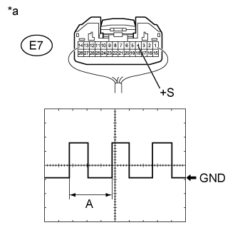
Connect an oscilloscope to the combination meter connector.
Check the waveform.
Measurement ConditionItem
| Content
|
Terminal No. (Symbol)
| E7-4 (+S) - Body ground
|
Tool setting
| 5 V/DIV., 20 ms./DIV.
|
Condition
| Vehicle is driven at approximately 20 km/h (12 mph)
|
- OK:
- Waveform is as shown in the illustration.
Text in Illustration*a
| Component with harness connected
(Combination Meter Assembly)
|
- HINT:
- When the system is functioning normally, one wheel revolution generates 4 pulses. As the vehicle speed increases, the width indicated by (A) in the illustration narrows.
| OK |
|
|
|
| REPLACE HEADLIGHT LEVELING ECU ASSEMBLY (Click here) |
|