Dtc C1380 Stop Light Control Relay Malfunction
Brake. Land Cruiser. Urj200, 202 Grj200 Vdj200
DESCRIPTION
WIRING DIAGRAM
INSPECTION PROCEDURE
CHECK PRE-CRASH SAFETY SYSTEM
CHECK HARNESS AND CONNECTOR (STP TERMINAL)
RECONFIRM DTC
DTC C1380 Stop Light Control Relay Malfunction |
DESCRIPTION
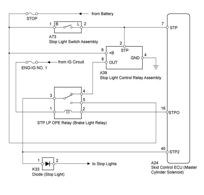
Upon receiving the hill-start assist control operating signal from the skid control ECU (master cylinder solenoid), the relay contact turns on and the stop light comes on.DTC Code
| DTC Detection Condition
| Trouble Area
|
C1380
| Either condition is met:
- When the voltage at the IG1 terminal is between 11 and 14 V and the stop light control relay drive output (STPO) is on, a signal is not input to the STP2 terminal for 5 seconds or more.
- When the voltage at the IG1 terminal is between 11 and 14 V and the stop light control relay drive output (STPO) is off, the signal at the STP terminal is different from the input signal at the STP2 terminal for 5 seconds or more.
| - Pre-crash safety system
- STOP fuse
- Harness or connector
- STP LP OPE relay (Brake light relay)
- Stop light control relay assembly
- Skid control ECU (Master cylinder solenoid)
|
WIRING DIAGRAM
INSPECTION PROCEDURE
- NOTICE:
- After replacing the master cylinder solenoid, perform zero point calibration and store the system information (Click here).
- Inspect the fuses for circuits related to this system before performing the following inspection procedure.
- HINT:
- When DTC C1425 is output together with DTC C1380, inspect and repair the trouble areas indicated by DTC C1425 first (Click here).
| 1.CHECK PRE-CRASH SAFETY SYSTEM |
Connect the GTS to the DLC3.
Turn the ignition switch off.
Turn the GTS on.
Enter the following menus: Body Electrical / Pre-Crash 2 / Trouble Codes.
Check for DTCs (Click here).
ResultResult
| Proceed to
|
DTC is not output
| A
|
DTC is output
| B
|
| | GO TO PRE-CRASH SAFETY SYSTEM (DIAGNOSTIC TROUBLE CODE CHART) (Click here) |
|
|
| 2.CHECK HARNESS AND CONNECTOR (STP TERMINAL) |
Turn the ignition switch off.
Disconnect the skid control ECU (master cylinder solenoid) connector.
Measure the voltage according to the value(s) in the table below.
- Standard Voltage:
Tester Connection
| Condition
| Specified Condition
|
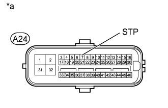
A24-7 (STP) - Body ground
| Brake pedal depressed
| 8 to 14 V
|
Brake pedal released
| Below 1.5 V
|
Text in Illustration*a
| Front view of wire harness connector
(to Skid Control ECU [Master Cylinder Solenoid])
|
| | REPAIR OR REPLACE HARNESS OR CONNECTOR (STP TERMINAL) |
|
|
Clear the DTCs (Click here).
Turn the ignition switch off.
Check if the same DTC is output (Click here).
ResultResult
| Proceed to
|
DTC is not output
| A
|
DTC is output (for LHD)
| B
|
DTC is output (for RHD)
| C
|