Dtc C1251 Open In Pump Motor Circuit
Brake. Land Cruiser. Urj200, 202 Grj200 Vdj200
DESCRIPTION
INSPECTION PROCEDURE
CHECK CONNECTION OF PUMP MOTOR WIRE HARNESS
CHECK RESISTANCE OF PUMP MOTOR WIRE HARNESS
RECONFIRM DTC
DTC C1251 Open in Pump Motor Circuit |
DESCRIPTION
The motor relay (semiconductor relay) is built into the master cylinder solenoid and drives the pump motor based on a signal from the skid control ECU (master cylinder solenoid).DTC Code
| DTC Detection Condition
| Trouble Area
|
C1251
| There is an open in the motor system circuit (motor input circuit).
| - Pump motor wire harness connection
- Brake booster with accumulator pump assembly
- Skid control ECU (Master cylinder solenoid)
|
INSPECTION PROCEDURE
- NOTICE:
- After replacing the master cylinder solenoid, perform zero point calibration (Click here).
- HINT:
- Remove the hydraulic brake booster assembly before the inspection (for LHD: Click here, for RHD: Click here).
| 1.CHECK CONNECTION OF PUMP MOTOR WIRE HARNESS |
Remove the hydraulic brake booster assembly (for LHD: Click here, for RHD: Click here).
Check the tightening torque of the 2 screws which secure the wire harness connecting the master cylinder solenoid and brake booster with accumulator pump assembly (for LHD: Click here, for RHD: Click here).
- OK:
- The harness is tightened to the specified torque.
| 2.CHECK RESISTANCE OF PUMP MOTOR WIRE HARNESS |
Using a screwdriver, remove the 2 screws and pull out the wire harness from the master cylinder solenoid.
Measure the resistance according to the value(s) in the table below.
- Standard Resistance:
Tester Connection
| Condition
| Specified Condition
|
Red wire terminal - Black wire terminal
| Always
| Below 2 Ω
|
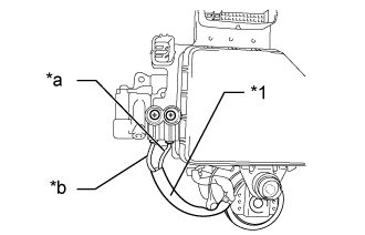
Text in Illustration*1
| Pump motor wire harness
|
*a
| Red wire
|
*b
| Black wire
|
- HINT:
Refer to the brake booster with accumulator pump assembly installation procedures:
- for LHD (Click here)
- for RHD (Click here)
| | REPLACE BRAKE BOOSTER WITH ACCUMULATOR PUMP ASSEMBLY |
|
|
Reassemble the hydraulic brake booster assembly (for LHD: Click here, for RHD: Click here).
Install the hydraulic brake booster assembly (for LHD: Click here, for RHD: Click here).
Clear the DTCs (Click here).
Turn the ignition switch off.
Check if the same DTC is output (Click here).
ResultResult
| Proceed to
|
DTC is not output
| A
|
DTC is output (for LHD)
| B
|
DTC is output (for RHD)
| C
|