Dtc C1241 Low Power Supply Voltage Malfunction
Brake. Land Cruiser. Urj200, 202 Grj200 Vdj200
DESCRIPTION
WIRING DIAGRAM
INSPECTION PROCEDURE
READ VALUE USING GTS (IG1 VOLTAGE VALUE)
RECONFIRM DTC
CHECK HARNESS AND CONNECTOR (IG1 TERMINAL)
CHECK HARNESS AND CONNECTOR (GND1, GND2 AND GND3 TERMINAL)
RECONFIRM DTC
DTC C1241 Low Power Supply Voltage Malfunction |
DESCRIPTION
If the voltage supplied to the IG1 terminal is within the DTC detection range due to malfunctions in components such as the battery and generator circuit, this DTC is stored.DTC Code
| DTC Detection Condition
| Trouble Area
|
C1241
| Either condition is met:
1. Both of the following conditions continue for at least 10 seconds.
- The vehicle speed is more than 3 km/h (2 mph).
- The IG1 terminal voltage is below 9.5 V.
2. All of the following conditions continue for at least 0.2 seconds.
- The solenoid relay remains on.
- The IG1 terminal voltage is below 9.5 V.
- The relay contact is open.
| - Battery
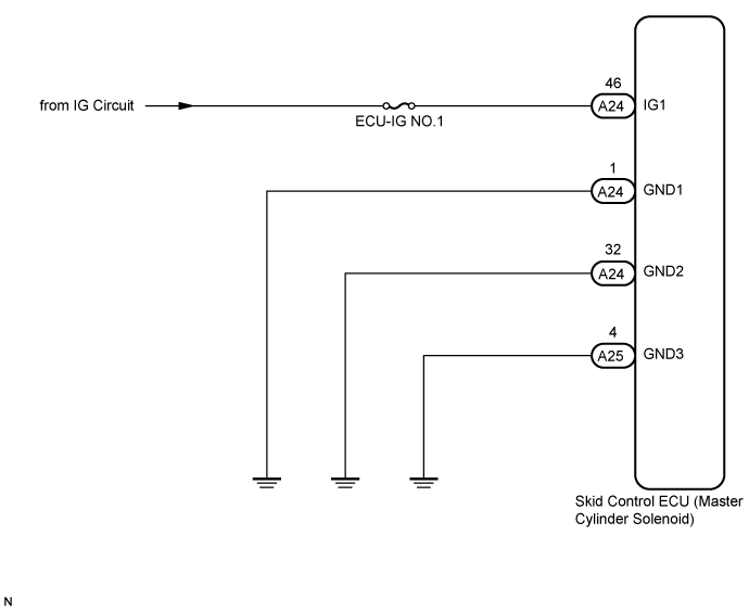
- ECU-IG NO.1 fuse
- Charging system
- Harness or connector
- Skid control ECU (Master cylinder solenoid)
|
WIRING DIAGRAM
INSPECTION PROCEDURE
- NOTICE:
- After replacing the master cylinder solenoid, perform zero point calibration and store the system information (Click here).
- Inspect the fuses for circuits related to this system before performing the following inspection procedure.
| 1.READ VALUE USING GTS (IG1 VOLTAGE VALUE) |
Turn the ignition switch off.
Connect the GTS to the DLC3.
Turn the ignition switch to ON.
Turn the GTS on.
Start the engine.
Enter the following menus: Chassis / ABS/VSC/TRC / Data List.
ABS/VSC/TRCTester Display
| Measurement Item/Range
| Normal Condition
| Diagnostic Note
|
IG1 Voltage Value
| IG1 voltage value/ Min.: 0.00 V, Max.: 20.00 V
| Ignition switch ON: 11 to 14 V
| -
|
Check the voltage output from the skid control ECU (master cylinder solenoid) displayed on the GTS.
- OK:
- The output voltage displayed on the GTS is within 11 to 14 V.
Clear the DTCs (Click here).
Turn the ignition switch off.
Check if the same DTCs are output (Click here).
- HINT:
- Reinstall the sensors, connectors, etc. and restore the previous vehicle conditions before rechecking for DTCs.
ResultResult
| Proceed to
|
DTC is output (for LHD)
| A
|
DTC is output (for RHD)
| B
|
DTC is not output (When troubleshooting in accordance with Diagnostic Trouble Code Chart)
| C
|
DTC is not output (When troubleshooting in accordance with Problem Symptoms Table)
| D
|
| |
|
| |
|
| | PROCEED TO NEXT SUSPECTED AREA SHOWN IN PROBLEM SYMPTOMS TABLE (Click here) |
|
|
| 3.CHECK HARNESS AND CONNECTOR (IG1 TERMINAL) |
Disconnect the skid control ECU (master cylinder solenoid) connector.
Measure the voltage according to the value(s) in the table below.
- Standard Voltage:
Tester Connection
| Switch Condition
| Specified Condition
|
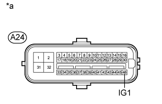
A24-46 (IG1) - Body ground
| Ignition switch ON
| 11 to 14 V
|
Text in Illustration*a
| Front view of wire harness connector
(to Skid Control ECU (Master Cylinder Solenoid))
|
| | REPAIR OR REPLACE HARNESS OR CONNECTOR |
|
|
| 4.CHECK HARNESS AND CONNECTOR (GND1, GND2 AND GND3 TERMINAL) |
Turn the ignition switch off.
Disconnect the skid control ECU (master cylinder solenoid) connectors.
Measure the resistance according to the value(s) in the table below.
- Standard Resistance:
Tester Connection
| Condition
| Specified Condition
|
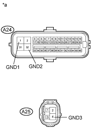
A24-1 (GND1) - Body ground
| Always
| Below 1 Ω
|
A24-32 (GND2) - Body ground
| Always
| Below 1 Ω
|
A25-4 (GND3) - Body ground
| Always
| Below 1 Ω
|
Text in Illustration*a
| Front view of wire harness connector
(to Skid Control ECU [Master Cylinder Solenoid])
|
| | REPAIR OR REPLACE HARNESS OR CONNECTOR |
|
|
Clear the DTCs (Click here).
Check if the same DTCs are output (Click here).
- HINT:
- Reinstall the sensors, connectors, etc. and restore the previous vehicle conditions before rechecking for DTCs.
ResultResult
| Proceed to
|
DTC is output (for LHD)
| A
|
DTC is output (for RHD)
| B
|
DTC is not output (When troubleshooting in accordance with Diagnostic Trouble Code Chart)
| C
|
DTC is not output (When troubleshooting in accordance with Problem Symptoms Table)
| D
|
| |
|
| |
|
| | PROCEED TO NEXT SUSPECTED AREA SHOWN IN PROBLEM SYMPTOMS TABLE (Click here) |
|
|