Anti-Lock Brake System Terminals Of Ecu
Brake. Land Cruiser. Urj200, 202 Grj200 Vdj200
TERMINALS OF ECU
TERMINAL INSPECTION
Anti-Lock Brake System -- Terminals Of Ecu |
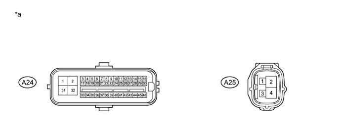
Text in Illustration*a
| Component without harness connected
(Skid Control ECU [Master Cylinder Solenoid])
| -
| -
|
Terminal No. (Symbol)
| Terminal Description
|
1 (GND1)
| Skid control ECU (Master cylinder solenoid) ground
|
2 (+BM1)
| Power supply for motor
|
3 (FR+)
| Front speed sensor RH power supply output
|
4 (FL-)
| Front speed sensor LH input
|
5 (RR+)
| Rear speed sensor RH power supply output
|
6 (RL-)
| Rear speed sensor LH input
|
7 (STP)
| Stop light switch assembly
|
11 (CANH)
| CAN communication terminal H
|
12 (SP1)
| Speedometer signal
|
14 (P)
| Rear differential lock detection switch (No. 1 Transfer indicator switch)
|
17 (FR-)
| Front speed sensor RH input
|
18 (FL+)
| Front speed sensor LH power supply output
|
19 (RR-)
| Rear speed sensor RH input
|
20 (RL+)
| Rear speed sensor LH power supply output
|
22 (VGS)
| Deceleration sensor power supply output
|
23 (GGND)
| Deceleration sensor ground
|
24 (TS)
| Sensor test terminal (Signal check switch)
|
25 (CANL)
| CAN communication terminal L
|
27 (EXI)
| Center differential lock detection switch (Transfer shift actuator assembly)
|
31 (+BS)
| Power supply for solenoid
|
32 (GND2)
| Skid control ECU (Master cylinder solenoid) ground
|
39 (GL1)
| Deceleration sensor input
|
41 (LBL)
| Brake fluid level warning switch (Brake master cylinder reservoir sub-assembly)
|
46 (IG1)
| IG1 power supply
|

Text in Illustration*a
| Component without harness connected
(Skid Control ECU [Master Cylinder Solenoid])
| -
| -
|
Terminal No. (Symbol)
| Terminal Description
|
1 (IG2)
| IG2 power supply
|
2 (+BM2)
| Power supply for motor
|
4 (GND3)
| Skid control ECU (Master cylinder solenoid) ground
|
Disconnect the connector and measure the voltage or resistance on the wire harness side.
- HINT:
- Voltage cannot be measured with the connector connected to the skid control ECU (master cylinder solenoid) as the connector is watertight.
Text in Illustration*a
| Front view of wire harness connector
(to Skid Control ECU [Master Cylinder Solenoid])
| -
| -
|
Terminal No. (Symbol)
| Wiring Color
| Terminal Description
| Condition
| Specified Condition
|
A24-2 (+BM1) - Body ground
| B
| Power supply for motor
(From battery)
| Always
| 11 to 14 V
|
A24-7 (STP) - Body ground
| R
| Stop light switch assembly
| Brake pedal depressed → released
| 8 to 14 V → Below 1.5 V
|
A24-31 (+BS) - Body ground
| W
| Power supply for solenoid
(From battery)
| Always
| 11 to 14 V
|
A24-41 (LBL) - Body ground
| P
| Brake fluid level warning switch (Brake master cylinder reservoir sub-assembly)
| Brake fluid level +/-5 mm (+/-0.197 in.) from the minimum level → maximum level
| Below 1 Ω → 1.9 to 2.1 kΩ
|
A24-46 (IG1) - Body ground
| V
| IG1 power supply
| Ignition switch off → ON
| Below 1 V → 11 to 14 V
|
A25-1 (IG2) - Body ground
| B
| IG2 power supply
| Ignition switch off → ON
| Below 1 V → 11 to 14 V
|
A25-2 (+BM2) - Body ground
| B
| Power supply for motor
(From battery)
| Always
| 11 to 14 V
|
A24-1 (GND1) - Body ground
| W-B
| Ground
| Always
| Below 1 Ω
|
A24-32 (GND2) - Body ground
| W-B
| Ground
| Always
| Below 1 Ω
|
A25-4 (GND3) - Body ground
| W-B
| Ground
| Always
| Below 1 Ω
|