Audio And Visual System (For Radio And Display Type) Avc-Lan Circuit
DESCRIPTION
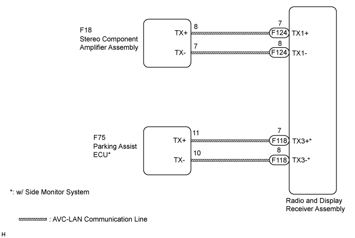
WIRING DIAGRAM
INSPECTION PROCEDURE
INSPECT RADIO AND DISPLAY RECEIVER ASSEMBLY
CHECK HARNESS AND CONNECTOR (AVC-LAN CIRCUIT)
INSPECT MALFUNCTIONING PARTS
AUDIO AND VISUAL SYSTEM (for Radio and Display Type) - AVC-LAN Circuit |
DESCRIPTION
Each audio system component connected to the AVC-LAN (communication bus) transfers switch signals using the audio visual communication local area network.If a short to +B or short to ground occurs in the AVC-LAN, the audio system will not function normally because communication is not possible.
WIRING DIAGRAM
INSPECTION PROCEDURE
- HINT:
- The radio and display receiver assembly is the master unit.
- When replacing the radio and display receiver assembly, it is necessary to perform the vehicle contract setting for Connected Services (w/ Connected Services Function).
| 1.INSPECT RADIO AND DISPLAY RECEIVER ASSEMBLY |
Remove the radio and display receiver assembly (Click here).
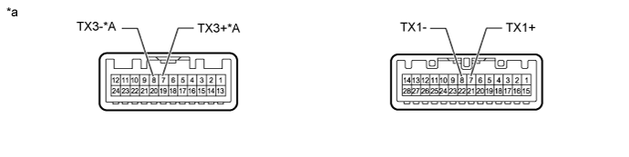
Text in Illustration*A
| w/ Side Monitor System
| -
| -
|
*a
| Component without harness connected
(Radio and Display Receiver Assembly)
| -
| -
|
Measure the resistance according to the value(s) in the table below.
- Standard Resistance:
Tester Connection
| Condition
| Specified Condition
|
7 (TX1+) - 8 (TX1-)
| Always
| 60 to 80 Ω
|
7 (TX3+) - 8 (TX3-)*
| Always
| 60 to 80 Ω
|
- *: w/ Side Monitor System
| | REPLACE RADIO AND DISPLAY RECEIVER ASSEMBLY (Click here) |
|
|
| 2.CHECK HARNESS AND CONNECTOR (AVC-LAN CIRCUIT) |
- *: w/ Side Monitor System
Disconnect the F118 and F124 radio and display receiver assembly connectors.
Disconnect the F18 stereo component amplifier assembly connector.
Disconnect the F75 parking assist ECU connector*.
Measure the resistance according to the value(s) in the table below.
- Standard Resistance:
Tester Connection
| Condition
| Specified Condition
|
F118-7 (TX3+) - F75-11 (TX+)*
| Always
| Below 1 Ω
|
F118-8 (TX3-) - F75-10 (TX-)*
| Always
| Below 1 Ω
|
F124-7 (TX1+) - F18-8 (TX+)
| Always
| Below 1 Ω
|
F124-8 (TX1-) - F18-7 (TX-)
| Always
| Below 1 Ω
|
F118-7 (TX3+) - Body ground*
| Always
| 10 kΩ or higher
|
F118-8 (TX3-) - Body ground*
| Always
| 10 kΩ or higher
|
F124-7 (TX1+) - Body ground
| Always
| 10 kΩ or higher
|
F124-8 (TX1-) - Body ground
| Always
| 10 kΩ or higher
|
| | REPAIR OR REPLACE HARNESS OR CONNECTOR |
|
|
| 3.INSPECT MALFUNCTIONING PARTS |
Disconnect and reconnect each slave unit one by one until the master unit returns to normal operation.
- HINT:
- Check all slave units.
- When disconnecting a slave unit causes the master unit to return to normal operation, this indicates that the slave unit is malfunctioning. Replace the malfunctioning slave unit.
- OK:
- Master unit returns to normal operation.
| | REPLACE RADIO AND DISPLAY RECEIVER ASSEMBLY (Click here) |
|
|
| OK |
|
|
|
| REPLACE MALFUNCTIONING PARTS |
|