Automatic Transmission Assembly Removal
Drivetrain. Land Cruiser. Urj200, 202 Grj200 Vdj200
PRECAUTION
DISCONNECT CABLE FROM NEGATIVE BATTERY TERMINAL
REMOVE FRONT PROPELLER SHAFT ASSEMBLY
REMOVE PROPELLER SHAFT ASSEMBLY
REMOVE EXHAUST PIPE
REMOVE STARTER ASSEMBLY
REMOVE UPPER RADIATOR SUPPORT SEAL
REMOVE FRONT FENDER SPLASH SHIELD SUB-ASSEMBLY LH
REMOVE FRONT FENDER SPLASH SHIELD SUB-ASSEMBLY RH
REMOVE NO. 1 ENGINE UNDER COVER SUB-ASSEMBLY
REMOVE NO. 2 ENGINE UNDER COVER
REMOVE OIL PAN PROTECTOR ASSEMBLY
REMOVE TRANSMISSION CASE COVER (w/ Cover)
DRAIN AUTOMATIC TRANSMISSION FLUID
DRAIN TRANSFER OIL
REMOVE FRONT FENDER APRON SEAL FRONT RH
REMOVE FRONT FENDER APRON SEAL REAR RH
DRAIN ENGINE COOLANT
REMOVE NO. 3 FRONT FLOOR HEAT INSULATOR
DISCONNECT FLOOR SHIFT GEAR SHIFTING ROD SUB-ASSEMBLY
REMOVE NO. 1 MANIFOLD STAY
REMOVE NO. 2 MANIFOLD STAY
REMOVE DRIVE PLATE AND TORQUE CONVERTER SETTING BOLT
DISCONNECT OIL COOLER TUBE
DISCONNECT GROUND CABLE
SUPPORT AUTOMATIC TRANSMISSION ASSEMBLY
REMOVE NO. 2 FRAME CROSSMEMBER SUB-ASSEMBLY
REMOVE REAR NO. 1 ENGINE MOUNTING INSULATOR
DISCONNECT WIRE HARNESS AND CONNECTOR
REMOVE TRANSFER ASSEMBLY
REMOVE AUTOMATIC TRANSMISSION ASSEMBLY
REMOVE WIRE HARNESS CLAMP BRACKET
REMOVE TORQUE CONVERTER ASSEMBLY
INSPECT TORQUE CONVERTER ASSEMBLY
Automatic Transmission Assembly -- Removal |
- NOTICE:
- After turning the engine switch off, waiting time may be required before disconnecting the cable from the battery terminal. Therefore, make sure to read the disconnecting the cable from the battery terminal notice before proceeding with work (Click here).
| 2. DISCONNECT CABLE FROM NEGATIVE BATTERY TERMINAL |
- NOTICE:
- When disconnecting the cable, some systems need to be initialized after the cable is reconnected (Click here).
| 3. REMOVE FRONT PROPELLER SHAFT ASSEMBLY |
(Click here)
| 4. REMOVE PROPELLER SHAFT ASSEMBLY |
(Click here)
(Click here)
| 6. REMOVE STARTER ASSEMBLY |
(Click here)
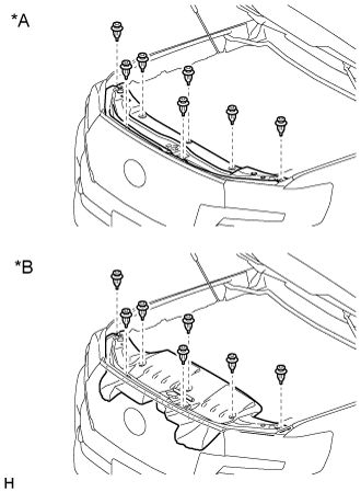
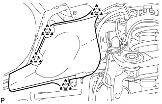
| 7. REMOVE UPPER RADIATOR SUPPORT SEAL |
Remove the 7 clips and upper radiator support seal.
Text in Illustration*A
| for Gasoline
|
*B
| for Diesel
|
| 8. REMOVE FRONT FENDER SPLASH SHIELD SUB-ASSEMBLY LH |
Remove the 3 bolts and screw.
Turn the clip indicated by the arrow in the illustration to remove the front fender splash shield sub-assembly LH.
| 9. REMOVE FRONT FENDER SPLASH SHIELD SUB-ASSEMBLY RH |
Remove the 3 bolts and 2 screws.
Turn the clip indicated by the arrow in the illustration to remove the front fender splash shield sub-assembly RH.
| 10. REMOVE NO. 1 ENGINE UNDER COVER SUB-ASSEMBLY |
Remove the 10 bolts and No. 1 engine under cover.
| 11. REMOVE NO. 2 ENGINE UNDER COVER |
Remove the 2 bolts and No. 2 engine under cover.
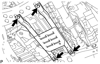
| 12. REMOVE OIL PAN PROTECTOR ASSEMBLY |
Remove the 4 bolts and oil pan protector assembly.
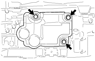
| 13. REMOVE TRANSMISSION CASE COVER (w/ Cover) |
Remove the 3 bolts and transmission case cover.
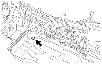
| 14. DRAIN AUTOMATIC TRANSMISSION FLUID |
Using a 5 mm hexagon socket wrench, remove the overflow plug and gasket from the automatic transmission assembly and drain the automatic transmission fluid.
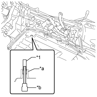
Using a 5 mm hexagon socket wrench, remove the transmission oil pan tube from the automatic transmission assembly and drain the automatic transmission fluid.
Text in Illustration*1
| Transmission Oil Pan Tube
|
*a
| Overflow Plug Hole
|
*b
| 5 mm Hexagon Socket Wrench
|
Using a 5 mm hexagon socket wrench, install the transmission oil pan tube to the automatic transmission assembly.
- Torque:
- 0.8 N*m{8 kgf*cm, 7 in.*lbf}
Using a 5 mm hexagon socket wrench, temporarily install the gasket and overflow plug to the automatic transmission assembly.
- Torque:
- 16 N*m{163 kgf*cm, 12 ft.*lbf}
except 1GR-FE:
Remove the 2 bolts and transfer dynamic damper.
Remove the 4 bolts and transfer heat insulator.
Remove the 7 bolts and lower transfer case protector.
Remove the filler plug and gasket.
Remove the drain plug and gasket, and drain the transfer oil.
| 16. REMOVE FRONT FENDER APRON SEAL FRONT RH |
Using a clip remover, remove the 3 clips and fender apron seal.
| 17. REMOVE FRONT FENDER APRON SEAL REAR RH |
Using a clip remover, remove the 4 clips and fender apron seal.
- CAUTION:
- Do not remove the radiator cap while the engine and radiator are still hot. Pressurized, hot engine coolant and steam may be released and cause serious burns.
Loosen the radiator drain cock plug.
- HINT:
- Collect the coolant in a container and dispose of it according to the regulations in your area.
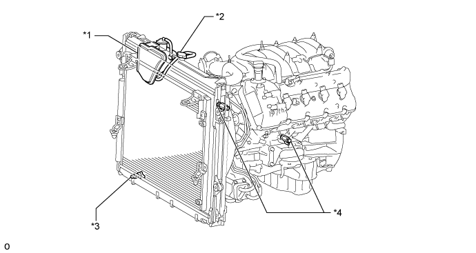
Remove the radiator cap. Then drain the coolant from the radiator.
Loosen the 2 cylinder block drain cock plugs. Then drain the coolant from the engine.
Tighten the 2 cylinder block drain cock plugs.
- Torque:
- 13 N*m{133 kgf*cm, 10 ft.*lbf}
Text in Illustration*1
| Radiator Reservoir
| *2
| Radiator Cap
|
*3
| Radiator Drain Cock Plug
| *4
| Cylinder Block Drain Cock Plug
|
Tighten the radiator drain cock plug by hand.
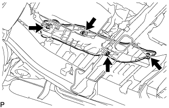
| 19. REMOVE NO. 3 FRONT FLOOR HEAT INSULATOR |
Remove the 4 nuts and No. 3 front floor heat insulator.
| 20. DISCONNECT FLOOR SHIFT GEAR SHIFTING ROD SUB-ASSEMBLY |
Remove the clip and pin and disconnect the floor shift gear shifting rod sub-assembly from the transmission control shaft lever.
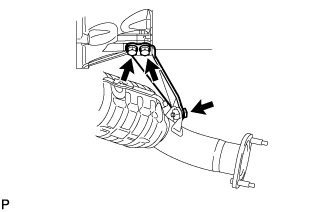
| 21. REMOVE NO. 1 MANIFOLD STAY |
Remove the 3 bolts and No. 1 manifold stay.
| 22. REMOVE NO. 2 MANIFOLD STAY |
Remove the 3 bolts and No. 2 manifold stay.
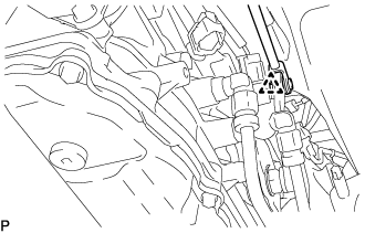
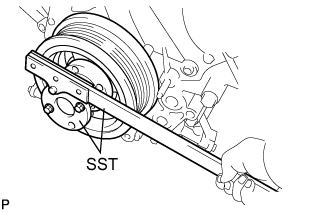
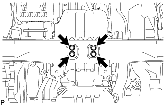
| 23. REMOVE DRIVE PLATE AND TORQUE CONVERTER SETTING BOLT |
Using SST, hold the crankshaft.
- SST
- 09213-70011(09213-70020)
09330-00021
Remove the 6 drive plate and torque converter setting bolts.
- HINT:
- Turn the crankshaft to remove the 6 drive plate and torque converter setting bolts.
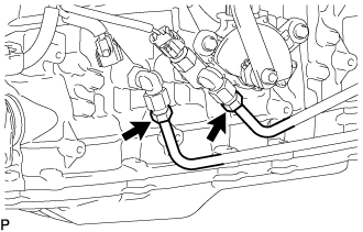
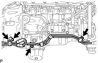
| 24. DISCONNECT OIL COOLER TUBE |
Using a 17 mm union nut wrench, disconnect the 2 oil cooler tubes from the oil cooler tube union.
Remove the 3 bolts and disconnect the oil cooler tube.
Remove the bolt and transmission oil cooler tube clamp sub-assembly.
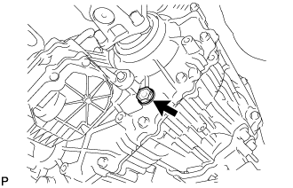
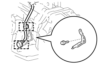
| 25. DISCONNECT GROUND CABLE |
Remove the bolt and disconnect the ground cable.
| 26. SUPPORT AUTOMATIC TRANSMISSION ASSEMBLY |
Support the transmission with a transmission jack. Lift the transmission slightly from the No. 3 frame crossmember sub-assembly.
- NOTICE:
- Support the oil pan bolts to prevent damage to the oil pan gasket.
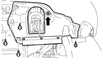
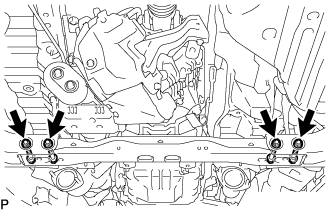
| 27. REMOVE NO. 2 FRAME CROSSMEMBER SUB-ASSEMBLY |
w/ Cover:
Remove the engine mounting hole cover.
Remove the 4 bolts of the rear No. 1 engine mounting insulator.
Remove the 4 nuts, 4 bolts and No. 2 frame crossmember sub-assembly.
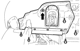
| 28. REMOVE REAR NO. 1 ENGINE MOUNTING INSULATOR |
Remove the 2 bolts and engine mounting heat insulator.
Remove the 4 bolts and rear No. 1 engine mounting insulator from the transmission.
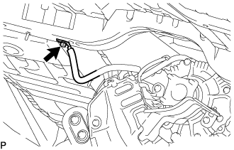
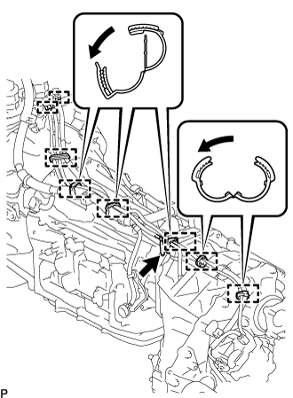
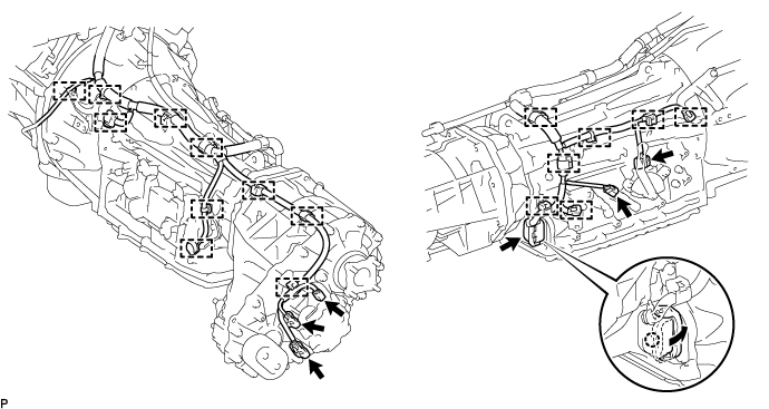
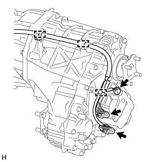
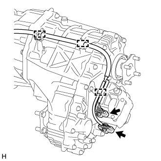
| 29. DISCONNECT WIRE HARNESS AND CONNECTOR |
Tilt the transmission downward.
- NOTICE:
- Support the oil pan bolts to prevent damage to the oil pan gasket.
- Make sure the cooling fan does not contact the fan shroud.
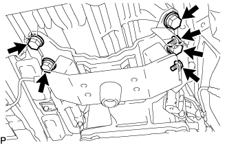
Disconnect the transfer breather hose sub-assembly from the automatic transmission assembly.
Detach the 6 clamps, 2 hose plugs and disconnect the transfer breather hose sub-assembly.
Disconnect the park/neutral position switch connector, 2 transmission wire connectors and 3 transfer control connectors.
- HINT:
- Detach the claw, pull the lever, and then disconnect the transmission wire connector.
Detach the 17 clamps and disconnect the wire harness.
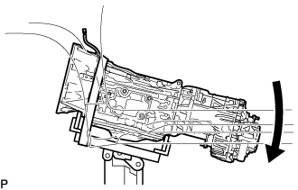
| 30. REMOVE TRANSFER ASSEMBLY |
Tilt the transmission downward.
- NOTICE:
- Make sure the cooling fan does not contact the fan shroud.
Detach the 2 clamps and disconnect the transfer breather hose sub-assembly.
w/ Temperature Sensor:
Detach the 3 clamps and disconnect the 3 connectors.
w/o Temperature Sensor:
Detach the 3 clamps and disconnect the 2 connectors.
Detach the 2 clamps.
Remove the bolt and bracket.
Support the transfer assembly with a transmission jack.
- NOTICE:
- Secure the transfer assembly to the transmission jack using a belt, etc. to prevent it from falling.
Remove the 8 bolts.
- CAUTION:
- Be sure to perform this procedure with several people as the transfer assembly is very heavy.
Pull the transfer assembly straight up and remove it from the transmission.
- NOTICE:
- Take care not to damage the adaptor oil seal with the transfer input shaft spline.
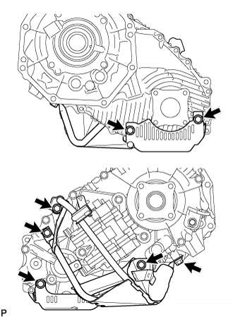
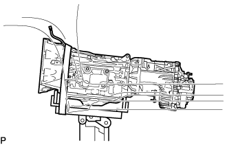
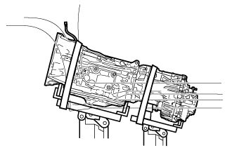
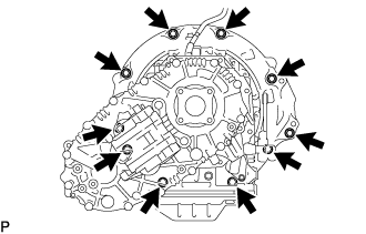
| 31. REMOVE AUTOMATIC TRANSMISSION ASSEMBLY |
Remove the 10 bolts and automatic transmission assembly.
- NOTICE:
- Do not use excess force to pry off the automatic transmission assembly.
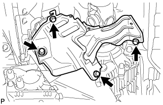
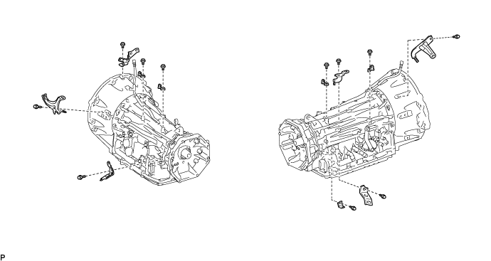
| 32. REMOVE WIRE HARNESS CLAMP BRACKET |
Remove the 11 bolts and 11 wire harness clamp brackets.
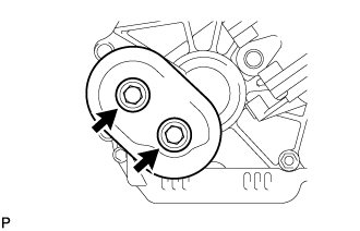
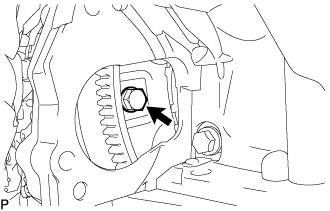
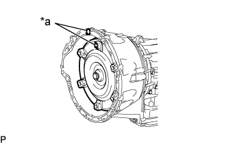
| 33. REMOVE TORQUE CONVERTER ASSEMBLY |
Put matchmarks on the automatic transmission case sub-assembly and the torque converter assembly.
Text in Illustration*a
| Matchmarks
|
Remove the torque converter assembly from the automatic transmission assembly.
- NOTICE:
- Remove the torque converter assembly from the input shaft horizontally.
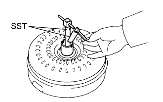
| 34. INSPECT TORQUE CONVERTER ASSEMBLY |
Inspect the one-way clutch.
Install SST into the inner race of the one-way clutch.
- SST
- 09350-32014(09351-32010)
Set SST so that it fits in the notch of the torque converter hub and the outer race of the one-way clutch.
- SST
- 09350-32014(09351-32020)
With the torque converter assembly standing on its side, check that the clutch locks when SST is turned counterclockwise and rotates freely and smoothly when SST is turned clockwise.
Text in Illustration*a
| Hold
|
*b
| Turn
|

| Difficult
|

| Smooth
|
If the results are not as specified, clean the torque converter assembly and recheck the one-way clutch.
If the results still are not as specified even after cleaning the torque converter assembly, replace the torque converter assembly.
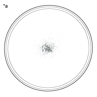
Determine the condition of the torque converter assembly.
Text in Illustration*a
| Sample showing maximum allowable amount of powder in ATF
|
Check that the following conditions are met:
- During the stall test or when the shift lever is in N, metallic sounds are not emitted from the torque converter assembly.
- The one-way clutch turns in one direction and locks in the other direction.
- The amount of powder in the ATF is not more than the sample shown in the illustration.
If the results are not as specified, replace the torque converter assembly.
- HINT:
- The sample illustration shows approximately 0.025 liters (0.026 US qts, 0.022 Imp. qts) of ATF taken from a removed torque converter assembly.
Replace the ATF in the torque converter assembly.
If the ATF is discolored and/or has a foul odor, stir the ATF in the torque converter assembly thoroughly and drain the ATF with the torque converter assembly facing upward.
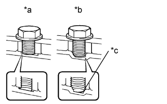
Prevent deformation of the torque converter and damage to the oil pump gear.
Text in Illustration*a
| CORRECT
|
*b
| INCORRECT
|
*c
| Bottom is damaged
|
When any marks due to interference are found on the end of a bolt for the torque converter assembly and on the bottom of the bolt hole, replace the bolt and torque converter assembly.
Make sure all of the bolts are the same length.
Make sure no spring washers are missing.