Automatic Transmission Assembly -- Installation |
| 1. INSPECT TORQUE CONVERTER ASSEMBLY |
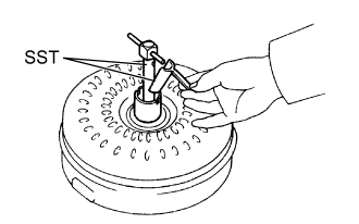
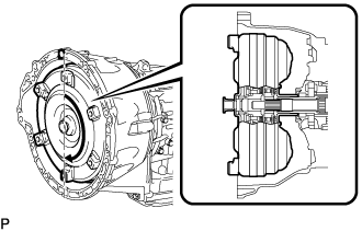
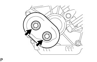
Inspect the one-way clutch.
Install SST into the inner race of the one-way clutch.
- SST
- 09350-32014(09351-32010)
Set SST so that it fits in the notch of the torque converter hub and the outer race of the one-way clutch.
- SST
- 09350-32014(09351-32020)
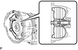
With the torque converter assembly standing on its side, check that the clutch locks when SST is turned counterclockwise and rotates freely and smoothly when SST is turned clockwise.
If the results are not as specified, clean the torque converter assembly and recheck the one-way clutch.Text in Illustration *a Hold *b Turn 
Difficult 
Smooth
If the results still are not as specified even after cleaning the torque converter assembly, replace the torque converter assembly.

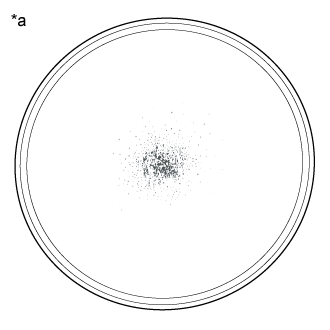
Determine the condition of the torque converter assembly.
Text in Illustration *a Sample showing maximum allowable amount of powder in ATF Check that the following conditions are met:
- During the stall test or when the shift lever is in N, metallic sounds are not emitted from the torque converter assembly.
- The one-way clutch turns in one direction and locks in the other direction.
- The amount of powder in the ATF is not more than the sample shown in the illustration.
- HINT:
- The sample illustration shows approximately 0.025 liters (0.026 US qts, 0.022 Imp. qts) of ATF taken from a removed torque converter assembly.
- During the stall test or when the shift lever is in N, metallic sounds are not emitted from the torque converter assembly.
 |
Replace the ATF in the torque converter assembly.
If the ATF is discolored and/or has a foul odor, stir the ATF in the torque converter assembly thoroughly and drain the ATF with the torque converter assembly facing upward.
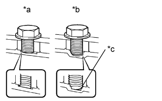
Prevent deformation of the torque converter and damage to the oil pump gear.
Text in Illustration *a CORRECT *b INCORRECT *c Bottom is damaged When any marks due to interference are found on the end of a bolt for the torque converter assembly and on the bottom of the bolt hole, replace the bolt and torque converter assembly.
Make sure all of the bolts are the same length.
Make sure no spring washers are missing.
 |
| 2. INSTALL TORQUE CONVERTER ASSEMBLY |
Engage the splines of the input shaft and turbine runner.
Text in Illustration *a Matchmarks
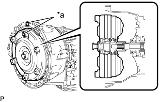 |
Engage the splines of the stator shaft and stator while turning the torque converter assembly.
- HINT:
- If the stator shaft splines are difficult to engage with the stator splines, move the torque converter back approximately 10 mm and engage the splines while rotating the torque converter.
 |
Turn the torque converter assembly to engage the key of the oil pump drive gear and the slot on the torque converter assembly.
 |
Using a vernier caliper and straightedge, measure dimension A between the surface of the engine that contacts the transmission and the surface of the drive plate that contacts the torque converter.
Text in Illustration *1 Engine Surface *2 Drive Plate Surface - NOTICE:
- Make sure to deduct the thickness of the straightedge.
 |
Using a vernier caliper and a straightedge, measure dimension B shown in the illustration and check that B is more than A measured in the first step.
- Standard distance:
- B = A + 1.00 mm (0.0394 in.) or more
- NOTICE:
- Make sure to deduct the thickness of the straightedge.
- If the transmission is installed to the engine with the torque converter not sufficiently inserted, the torque converter may be damaged.
 |
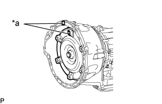
| 3. INSTALL WIRE HARNESS CLAMP BRACKET |
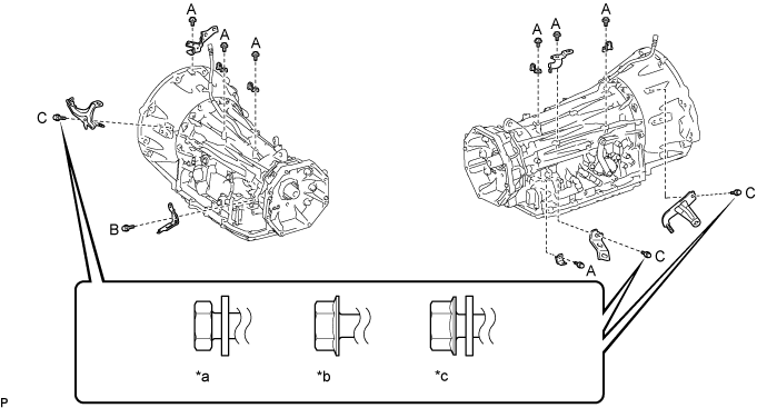
| *a | for Type A | *b | for Type B |
| *c | for Type C | - | - |
Install the 11 bolts and 11 wire harness clamp brackets.
- Torque:
- Bolt A:
- 8.0 N*m{82 kgf*cm, 71 in.*lbf}
- Bolt B:
- 29 N*m{296 kgf*cm, 21 ft.*lbf}
- Bolt C (for Type A):
- 7.5 N*m{76 kgf*cm, 66 in.*lbf}
- Bolt C (for Type B):
- 8.0 N*m{82 kgf*cm, 71 in.*lbf}
- Bolt C (for Type C):
- 13 N*m{132 kgf*cm, 10 ft.*lbf}
- NOTICE:
- Check whether the bolt being used is Type A or Type B or Type C, and then tighten the bolt using the appropriate torque.
| 4. INSTALL AUTOMATIC TRANSMISSION ASSEMBLY |
Apply clutch spline grease to the surface of the crankshaft that contacts the torque converter centerpiece.
- Clutch spline grease:
- Toyota Genuine Clutch Spline Grease or equivalent
- Maximum grease amount:
- Approximately 1 g (0.0353 oz.)
Text in Illustration *1 Torque Converter Centerpiece *2 Knock Pin *3 Crankshaft 
Clutch Spline Grease
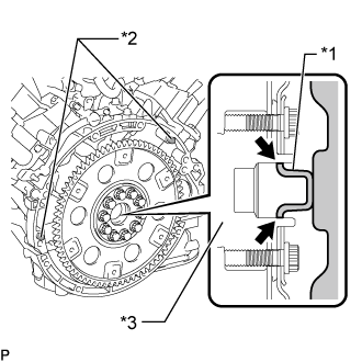 |
Confirm that the 2 knock pins are on the surface of the engine block that contacts the transmission.
Make sure that the mark is positioned as shown in the illustration.
Text in Illustration *a Matchmarks
 |
Keeping the engine and automatic transmission assembly horizontal, align the knock pins with the holes on the automatic transmission assembly and install the 10 bolts shown in the illustration.
- Torque:
- for bolt A:
- 71 N*m{724 kgf*cm, 52 ft.*lbf}
- for bolt B:
- 37 N*m{377 kgf*cm, 27 ft.*lbf}
 |
| 5. INSTALL TRANSFER ASSEMBLY |
Install the transfer assembly with the 8 bolts.
- Torque:
- 40 N*m{408 kgf*cm, 30 ft.*lbf}
- NOTICE:
- Take care not to damage the adaptor oil seal with the transfer input shaft spline.
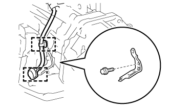
Install the bracket with the bolt.
- Torque:
- 29 N*m{296 kgf*cm, 21 ft.*lbf}
 |
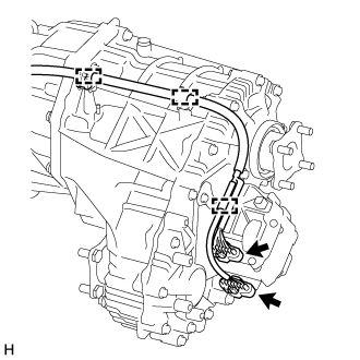
Attach the 2 clamps.
w/ Temperature Sensor:
Connect the 3 connectors and attach the 3 clamps.
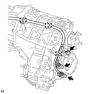 |
w/o Temperature Sensor:
Connect the 2 connectors and attach the 3 clamps.
 |
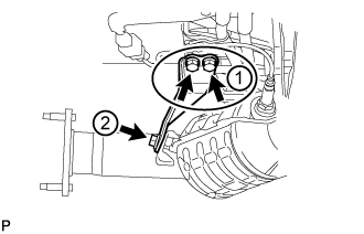
Connect the transfer breather hose sub-assembly and attach the 2 clamps.
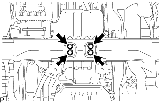
| 6. CONNECT WIRE HARNESS AND CONNECTOR |
Connect the park/neutral position switch connector, 2 transmission wire connectors and 3 transfer control connectors.
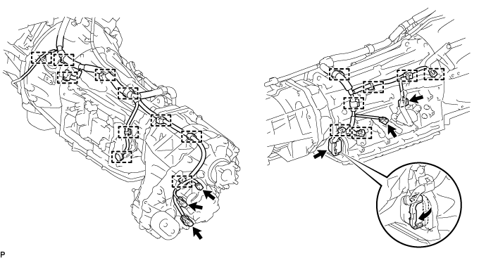
- HINT:
- Push up the lever until the claw of the transmission wire connector makes a connection sound.
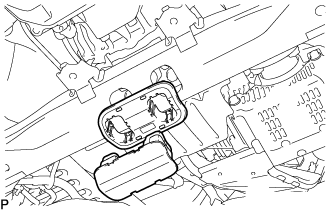
Attach the 17 clamps and connect the wire harness.
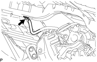
Connect the transfer breather hose sub-assembly to the automatic transmission assembly.
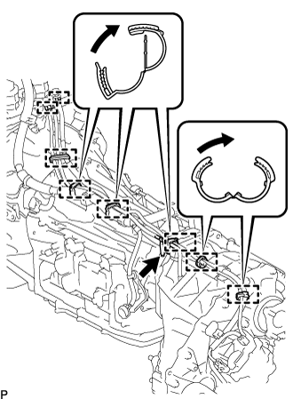 |
Attach the 6 clamps 2 hose plugs and connect the transfer breather hose sub-assembly.
Tilt up the automatic transmission.
| 7. INSTALL REAR NO. 1 ENGINE MOUNTING INSULATOR |
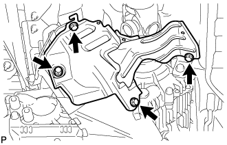
Install the rear No. 1 engine mounting insulator to the transmission with the 4 bolts.
- Torque:
- 59 N*m{602 kgf*cm, 44 ft.*lbf}
 |
Install the engine mounting heat insulator with the 2 bolts.
- Torque:
- 12 N*m{122 kgf*cm, 9 ft.*lbf}
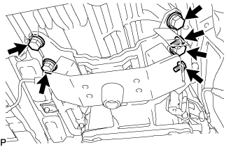
| 8. INSTALL NO. 2 FRAME CROSSMEMBER SUB-ASSEMBLY |
Temporarily install the No. 2 frame crossmember sub-assembly to the frame with the 4 bolts and 4 nuts.
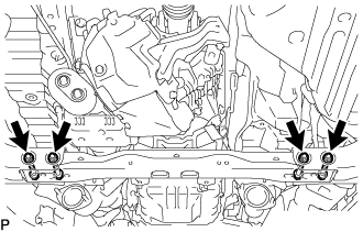 |
Lower the transmission assembly, and then install the rear No. 1 engine mounting insulator to the No. 2 frame crossmember sub-assembly with the 4 bolts.
- Torque:
- 37 N*m{377 kgf*cm, 27 ft.*lbf}
 |
Tighten the No. 2 frame crossmember sub-assembly with the 4 bolts and 4 nuts.
- Torque:
- 110 N*m{1122 kgf*cm, 81 ft.*lbf}
w/ Cover:
Install the engine mounting hole cover.
 |
| 9. CONNECT GROUND CABLE |
Connect the ground cable with the bolt.
- Torque:
- 8.4 N*m{85 kgf*cm, 74 in.*lbf}
 |
| 10. CONNECT OIL COOLER TUBE |
Install the transmission oil cooler tube clamp sub-assembly with bolt (labeled C).
- Torque:
- 14 N*m{143 kgf*cm, 10 ft.*lbf}
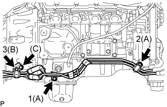 |
Temporarily install the oil cooler tube with the 3 bolts and 2 oil cooler tube unions.
Tighten the 3 bolts in the sequence shown in the illustration.
- Torque:
- for bolt A:
- 14 N*m{143 kgf*cm, 10 ft.*lbf}
- for bolt B:
- 8.0 N*m{82 kgf*cm, 71 in.*lbf}
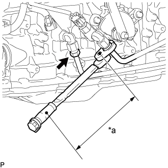
Tighten the 2 oil cooler tubes.
- Torque:
- Specified tightening torque:
- 34 N*m{347 kgf*cm, 25 ft.*lbf}
- HINT:
- Calculate the torque wrench reading when changing the fulcrum length of the torque wrench.
(Click here) - When using 17 mm union nut wrench (fulcrum length of 30 mm (1.18 in.)) + torque wrench (fulcrum length of 180 mm (7.09 in.)): 29 N*m (297 kgf*cm, 21 ft.*lbf)
Text in Illustration *a Torque Wrench Fulcrum Length
 |
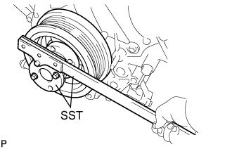
| 11. INSTALL DRIVE PLATE AND TORQUE CONVERTER SETTING BOLT |
Using SST, hold the crankshaft.
- SST
- 09213-70011(09213-70020)
09330-00021
 |
Install the 6 drive plate and torque converter setting bolts.
- Torque:
- 53 N*m{535 kgf*cm, 39 ft.*lbf}
- NOTICE:
- First install the black-colored bolt, and then the remaining 5 silver colored bolts.
- Turn the crankshaft to install the 6 drive plate and torque converter setting bolts.
 |
| 12. INSTALL NO. 2 MANIFOLD STAY |
Temporarily install the No. 2 manifold stay with the 3 bolts.
Tighten the 3 bolts in the order shown in the illustration.
- Torque:
- 40 N*m{408 kgf*cm, 30 ft.*lbf}
 |
| 13. INSTALL NO. 1 MANIFOLD STAY |
Temporarily install the No. 1 manifold stay with the 3 bolts.
Tighten the 3 bolts in the order shown in the illustration.
- Torque:
- 40 N*m{408 kgf*cm, 30 ft.*lbf}
 |
| 14. CONNECT FLOOR SHIFT GEAR SHIFTING ROD SUB-ASSEMBLY |
Turn the transmission control shaft lever of the park/neutral position switch counterclockwise until it stops, and then turn it clockwise 2 notches to set it to the N position.
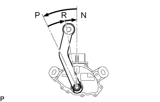 |
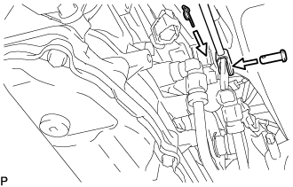
Move the shift lever to N.
Connect the floor shift gear shifting rod sub-assembly to the transmission control shaft lever with the pin and a new clip.
 |
| 15. INSTALL NO. 3 FRONT FLOOR HEAT INSULATOR |
Install the No. 3 front floor heat insulator with the 4 nuts.
- Torque:
- 5.0 N*m{51 kgf*cm, 44 in.*lbf}
| 16. INSTALL STARTER ASSEMBLY |
| 17. INSTALL EXHAUST PIPE |
| 18. INSTALL PROPELLER SHAFT ASSEMBLY |
| 19. INSTALL FRONT PROPELLER SHAFT ASSEMBLY |
| 20. CONNECT CABLE TO NEGATIVE BATTERY TERMINAL |
- NOTICE:
- When disconnecting the cable, some systems need to be initialized after the cable is reconnected (Click here).
| 21. ADD AUTOMATIC TRANSMISSION FLUID |
| 22. ADD TRANSFER OIL |
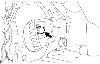
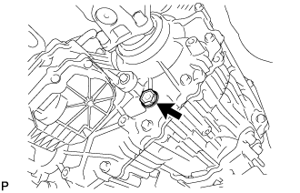
Install a new gasket onto the drain plug and then install the plug.
- Torque:
- 37 N*m{377 kgf*cm, 27 ft.*lbf}
 |
Add oil so that the oil level is between 0 to 5.0 mm (0 to 0.197 in.) from the bottom lip of the filler plug hole.
- NOTICE:
- Add oil slowly.
- Add oil a little at a time, waiting several minutes between each addition of oil.
 |
Wait approximately 5 minutes and check that the oil level has not changed.
Install a new gasket onto the filler plug and then install the plug.
- Torque:
- 37 N*m{377 kgf*cm, 27 ft.*lbf}
 |
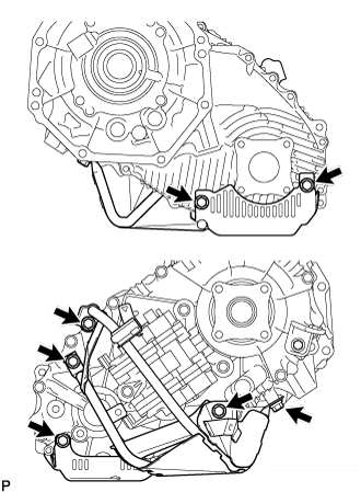
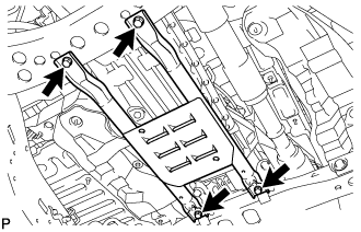
Install the lower transfer case protector with the 7 bolts.
- Torque:
- 14 N*m{139 kgf*cm, 10 ft.*lbf}
 |
Install the transfer heat insulator with the 4 bolts.
- Torque:
- 30 N*m{306 kgf*cm, 22 ft.*lbf}
 |
except 1GR-FE:
Install the transfer dynamic damper with the 2 bolts.- Torque:
- 12 N*m{122 kgf*cm, 9 ft.*lbf}
 |
| 23. ADD ENGINE COOLANT |
Add engine coolant.
- Standard Capacity:
Item Specified Condition with rear heater 16.2 liters (17.1 US qts, 14.3 Imp. qts) without rear heater 13.4 liters (14.2 US qts, 11.8 Imp. qts)
- NOTICE:
- Do not substitute plain water for engine coolant.
- HINT:
- TOYOTA vehicles are filled with TOYOTA SLLC at the factory. In order to avoid damage to the engine cooling system and other technical problems, only use TOYOTA SLLC or similar high quality ethylene glycol based non-silicate, non-amine, non-nitrite, non-borate coolant with long-life hybrid organic acid technology (coolant with long-life hybrid organic acid technology consists of a combination of low phosphates and organic acids).
Slowly pour coolant into the radiator reservoir until it reaches the F line.
Install the reservoir cap.
Press the No. 1 and No. 2 radiator hoses several times by hand, and then check the coolant level. If the coolant level is low, add coolant.
Install the radiator cap.
Start the engine and warm it up until the thermostat opens.
- HINT:
- The thermostat opening timing can be confirmed by pressing the radiator inlet hose by hand, and checking when the engine coolant starts to flow inside the hose.
Maintain the engine speed at 2000 to 2500 rpm.
- NOTICE:
- Make sure that the radiator reservoir still has some coolant in it.
- Pay attention to the needle of the water temperature meter. Make sure that the needle does not show an abnormally high temperature.
- If there is not enough coolant, the engine may burn out or overheat.
- Immediately after starting the engine, if the radiator reservoir does not have any coolant, perform the following: 1) stop the engine, 2) wait until the coolant has cooled down, and 3) add coolant until the coolant is filled to the F line.
- Run the engine at 2000 rpm until the coolant level has stabilized.
Press the No. 1 and No. 2 radiator hoses several times by hand to bleed air.
- CAUTION:
- Wear protective gloves.
- Be careful as the radiator hoses are hot.
- Keep your hands away from the fan.
Stop the engine, and wait until the engine coolant cools down to ambient temperature.
- CAUTION:
- Do not remove the radiator cap while the engine and radiator are still hot. Pressurized, hot engine coolant and steam may be released and cause serious burns.
Check that the coolant level is between the F and L lines.
If the coolant level is below the L line, repeat all of the procedures above.
If the coolant level is above the F line, drain coolant so that the coolant level is between the F and L lines.
| 24. INSPECT FOR AUTOMATIC TRANSMISSION FLUID LEAK |
Start the engine. Make sure that there are no automatic transmission fluid leaks from the areas that were worked on.
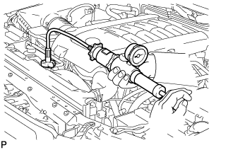
| 25. INSPECT FOR ENGINE COOLANT LEAK |
 |
- CAUTION:
- Do not remove the radiator cap while the engine and radiator are still hot. Pressurized, hot engine coolant and steam may be released and cause serious burns.
Fill the radiator with coolant and attach a radiator cap tester.
Warm up the engine.
Using the radiator cap tester, increase the pressure inside the radiator to 123 kPa (1.3 kgf/cm2, 18 psi), and check that the pressure does not drop.
If the pressure drops, check the hoses, radiator and water pump for leaks. If no external leaks are found, check the heater core, cylinder block and head.
| 26. INSPECT SHIFT LEVER POSITION |
| 27. INSPECT FOR EXHAUST GAS LEAK |
| 28. INSTALL FRONT FENDER APRON SEAL REAR RH |
Install the fender apron seal with the 4 clips.
| 29. INSTALL FRONT FENDER APRON SEAL FRONT RH |
Install the fender apron seal with the 3 clips.
| 30. INSTALL TRANSMISSION CASE COVER (w/ Cover) |
Install the transmission case cover with the 3 bolts.
- Torque:
- 13 N*m{131 kgf*cm, 9 ft.*lbf}
| 31. INSTALL OIL PAN PROTECTOR ASSEMBLY |
Install the oil pan protector with the 4 bolts.
- Torque:
- 50 N*m{510 kgf*cm, 37 ft.*lbf}
 |
| 32. INSTALL NO. 2 ENGINE UNDER COVER |
Install the No. 2 engine under cover with the 2 bolts.
- Torque:
- 29 N*m{296 kgf*cm, 21 ft.*lbf}
| 33. INSTALL NO. 1 ENGINE UNDER COVER SUB-ASSEMBLY |
Install the No. 1 engine under cover with the 10 bolts.
- Torque:
- 29 N*m{296 kgf*cm, 21 ft.*lbf}
| 34. INSTALL FRONT FENDER SPLASH SHIELD SUB-ASSEMBLY LH |
Push in the clip to install the front fender splash shield sub-assembly LH.
Install the 3 bolts and screw.
| 35. INSTALL FRONT FENDER SPLASH SHIELD SUB-ASSEMBLY RH |
Push in the clip to install the front fender splash shield sub-assembly RH.
Install the 3 bolts and 2 screws.
| 36. INSTALL UPPER RADIATOR SUPPORT SEAL |
Install the upper radiator support seal with the 7 clips.
| 37. RESET MEMORY |
Perform the Reset Memory procedures (A/T initialization) (Click here).