DESCRIPTION
WIRING DIAGRAM
INSPECTION PROCEDURE
CLEAR DTC
CHECK FOR DTC
CHECK OPTIONAL COMPONENTS (INCLUDING ASSOCIATED WIRING)
REMOVE OPTIONAL COMPONENTS (INCLUDING ASSOCIATED WIRING)
CLEAR DTC
CHECK FOR DTC
CHECK OPERATION
CHECK HARNESS AND CONNECTOR (TELEVISION DISPLAY ASSEMBLY LH POWER SOURCE)
CHECK HARNESS AND CONNECTOR (MULTI-DISPLAY CONTROLLER SUB-ASSEMBLY - TELEVISION DISPLAY ASSEMBLY LH)
CHECK TELEVISION DISPLAY ASSEMBLY LH
CHECK HARNESS AND CONNECTOR (MULTI-DISPLAY CONTROLLER SUB-ASSEMBLY - TELEVISION DISPLAY ASSEMBLY LH)
CHECK HARNESS AND CONNECTOR (TELEVISION DISPLAY ASSEMBLY RH POWER SOURCE)
CHECK HARNESS AND CONNECTOR (MULTI-DISPLAY CONTROLLER SUB-ASSEMBLY - TELEVISION DISPLAY ASSEMBLY RH)
CHECK TELEVISION DISPLAY ASSEMBLY RH
CHECK HARNESS AND CONNECTOR (MULTI-DISPLAY CONTROLLER SUB-ASSEMBLY - TELEVISION DISPLAY ASSEMBLY RH)
DTC B15CE Seatback Display Disconnected |
DESCRIPTION
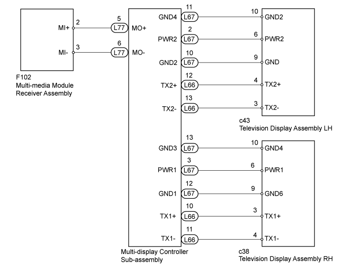
The television display assembly and multi-display controller sub-assembly are connected by an AVC-LAN communication line.The multi-media module receiver assembly is connected to the multi-display controller sub-assembly by a MOST communication line.This DTC will be stored when an AVC-LAN communication error occurs between the multi-display controller sub-assembly and television display assembly.DTC Code
| DTC Detection Condition
| Trouble Area
|
B15CE
| Either condition is met:
- The television display assembly is not connected while the engine switch is on (IG) or (ACC).
- Communication between the master unit and television display assembly is not possible when the engine is started.
| - Television display assembly power source circuit
- AVC-LAN circuit between multi-display controller sub-assembly and television display assembly
- Multi-display controller sub-assembly
- Television display assembly LH
- Television display assembly RH
|
- HINT:
- Even if no fault is present, this DTC may be stored depending on the battery condition or engine start voltage.
- The multi-media module receiver assembly is the master unit.
WIRING DIAGRAM
INSPECTION PROCEDURE
Clear the DTCs (Click here).
Check for DTCs and check if the same trouble occurs again (Click here).
- OK:
- No DTCs are output.
| 3.CHECK OPTIONAL COMPONENTS (INCLUDING ASSOCIATED WIRING) |
Check that optional components (including associated wiring) which generate radio waves are not installed.
ResultResult
| Proceed to
|
Optional components (including associated wiring) are installed
| A
|
Optional components (including associated wiring) are not installed
| B
|
| 4.REMOVE OPTIONAL COMPONENTS (INCLUDING ASSOCIATED WIRING) |
Remove optional components (including associated wiring).
- NOTICE:
- Do not remove optional components or associated wiring without the permission of the customer.
Clear the DTCs (Click here).
Check for DTCs and check if the same trouble occurs again (Click here).
- OK:
- No DTCs are output.
Check which television display assembly does not operate.
ResultResult
| Proceed to
|
Television display assembly LH does not operate
| A
|
Television display assembly RH does not operate
| B
|
| 8.CHECK HARNESS AND CONNECTOR (TELEVISION DISPLAY ASSEMBLY LH POWER SOURCE) |
Disconnect the television display assembly LH connector.
Measure the voltage according to the value(s) in the table below.
- Standard Voltage:
Tester Connection
| Switch Condition
| Specified Condition
|
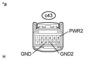
c43-6 (PWR2) - c43-9 (GND)
| Engine switch on (IG)
| 11 to 14 V
|
c43-6 (PWR2) - c43-10 (GND2)
| Engine switch on (IG)
| 11 to 14 V
|
Text in Illustration*a
| Front view of wire harness connector
(to Television Display Assembly LH)
|
| 9.CHECK HARNESS AND CONNECTOR (MULTI-DISPLAY CONTROLLER SUB-ASSEMBLY - TELEVISION DISPLAY ASSEMBLY LH) |
Disconnect the L66 multi-display controller sub-assembly connector.
Disconnect the c43 television display assembly LH connector.
Measure the resistance according to the value(s) in the table below.
- Standard Resistance:
Tester Connection
| Condition
| Specified Condition
|
L66-12 (TX2+) - c43-4 (TX2+)
| Always
| Below 1 Ω
|
L66-13 (TX2-) - c43-3 (TX2-)
| Always
| Below 1 Ω
|
L66-12 (TX2+) - Body ground
| Always
| 10 kΩ or higher
|
L66-13 (TX2-) - Body ground
| Always
| 10 kΩ or higher
|
| | REPAIR OR REPLACE HARNESS OR CONNECTOR |
|
|
| 10.CHECK TELEVISION DISPLAY ASSEMBLY LH |
Replace the television display assembly LH (Click here).
Clear the DTCs (Click here).
Check for DTCs and check if the same trouble occurs again.
- OK:
- No DTCs are output.
| | REPLACE MULTI-DISPLAY CONTROLLER SUB-ASSEMBLY (Click here) |
|
|
| OK |
|
|
|
| END (TELEVISION DISPLAY ASSEMBLY LH IS DEFECTIVE) |
|
| 11.CHECK HARNESS AND CONNECTOR (MULTI-DISPLAY CONTROLLER SUB-ASSEMBLY - TELEVISION DISPLAY ASSEMBLY LH) |
Disconnect the L67 multi-display controller sub-assembly connector.
Disconnect the c43 television display assembly LH connector.
Measure the resistance according to the value(s) in the table below.
- Standard Resistance:
Tester Connection
| Condition
| Specified Condition
|
L67-2 (PWR2) - c43-6 (PWR2)
| Always
| Below 1 Ω
|
L67-10 (GND2) - c43-9 (GND)
| Always
| Below 1 Ω
|
L67-11 (GND4) - c43-10 (GND2)
| Always
| Below 1 Ω
|
L67-2 (PWR2) - Body ground
| Always
| 10 kΩ or higher
|
L67-10 (GND2) - Body ground
| Always
| 10 kΩ or higher
|
L67-11 (GND4) - Body ground
| Always
| 10 kΩ or higher
|
| | REPAIR OR REPLACE HARNESS OR CONNECTOR |
|
|
| OK |
|
|
|
| REPLACE MULTI-DISPLAY CONTROLLER SUB-ASSEMBLY (Click here) |
|
| 12.CHECK HARNESS AND CONNECTOR (TELEVISION DISPLAY ASSEMBLY RH POWER SOURCE) |
Disconnect the television display assembly RH connector.
Measure the voltage according to the value(s) in the table below.
- Standard Voltage:
Tester Connection
| Switch Condition
| Specified Condition
|
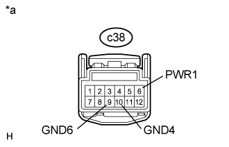
c38-6 (PWR1) - c38-9 (GND6)
| Engine switch on (IG)
| 11 to 14 V
|
c38-6 (PWR1) - c38-10 (GND4)
| Engine switch on (IG)
| 11 to 14 V
|
Text in Illustration*a
| Front view of wire harness connector
(to Television Display Assembly RH)
|
| 13.CHECK HARNESS AND CONNECTOR (MULTI-DISPLAY CONTROLLER SUB-ASSEMBLY - TELEVISION DISPLAY ASSEMBLY RH) |
Disconnect the L66 multi-display controller sub-assembly connector.
Disconnect the c38 television display assembly RH connector.
Measure the resistance according to the value(s) in the table below.
- Standard Resistance:
Tester Connection
| Condition
| Specified Condition
|
L66-10 (TX1+) - c38-3 (TX1+)
| Always
| Below 1 Ω
|
L66-11 (TX1-) - c38-4 (TX1-)
| Always
| Below 1 Ω
|
L66-10 (TX1+) - Body ground
| Always
| 10 kΩ or higher
|
L66-11 (TX1-) - Body ground
| Always
| 10 kΩ or higher
|
| | REPAIR OR REPLACE HARNESS OR CONNECTOR |
|
|
| 14.CHECK TELEVISION DISPLAY ASSEMBLY RH |
Replace the television display assembly RH (Click here).
Clear the DTCs (Click here).
Check for DTCs and check if the same trouble occurs again.
- OK:
- No DTCs are output.
| | REPLACE MULTI-DISPLAY CONTROLLER SUB-ASSEMBLY (Click here) |
|
|
| OK |
|
|
|
| END (TELEVISION DISPLAY ASSEMBLY RH IS DEFECTIVE) |
|
| 15.CHECK HARNESS AND CONNECTOR (MULTI-DISPLAY CONTROLLER SUB-ASSEMBLY - TELEVISION DISPLAY ASSEMBLY RH) |
Disconnect the L67 multi-display controller sub-assembly connector.
Disconnect the c38 television display assembly RH connector.
Measure the resistance according to the value(s) in the table below.
- Standard Resistance:
Tester Connection
| Condition
| Specified Condition
|
L67-3 (PWR1) - c38-6 (PWR1)
| Always
| Below 1 Ω
|
L67-12 (GND1) - c38-9 (GND6)
| Always
| Below 1 Ω
|
L67-13 (GND3) - c38-10 (GND4)
| Always
| Below 1 Ω
|
L67-3 (PWR1) - Body ground
| Always
| 10 kΩ or higher
|
L67-12 (GND1) - Body ground
| Always
| 10 kΩ or higher
|
L67-13 (GND3) - Body ground
| Always
| 10 kΩ or higher
|
| | REPAIR OR REPLACE HARNESS OR CONNECTOR |
|
|
| OK |
|
|
|
| REPLACE MULTI-DISPLAY CONTROLLER SUB-ASSEMBLY (Click here) |
|