Dtc B15D3 Stereo Component Amplifier Disconnected
DESCRIPTION
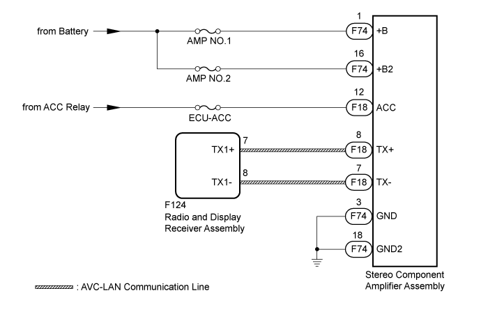
WIRING DIAGRAM
INSPECTION PROCEDURE
CHECK OPTIONAL COMPONENTS (INCLUDING ASSOCIATED WIRING)
REMOVE OPTIONAL COMPONENTS (INCLUDING ASSOCIATED WIRING)
CHECK FOR DTC
CHECK HARNESS AND CONNECTOR (STEREO COMPONENT AMPLIFIER ASSEMBLY - BATTERY AND BODY GROUND)
INSPECT RADIO AND DISPLAY RECEIVER ASSEMBLY
CHECK HARNESS AND CONNECTOR (RADIO AND DISPLAY RECEIVER ASSEMBLY - STEREO COMPONENT AMPLIFIER ASSEMBLY)
CHECK STEREO COMPONENT AMPLIFIER ASSEMBLY
DTC B15D3 Stereo Component Amplifier Disconnected |
DESCRIPTION
The radio and display receiver assembly and stereo component amplifier assembly are connected by the AVC-LAN communication line.This DTC is stored when an AVC-LAN communication error occurs between the radio and display receiver assembly.DTC Code
| DTC Detection Condition
| Trouble Area
|
B15D3
| When either condition below is met:
- The stereo component amplifier assembly is/was not connected while the engine switch is/was turned to on (IG)or on (ACC)
- Communication between the master unit and the stereo component amplifier assembly is not possible when the engine is started
| - Stereo component amplifier assembly power source circuit
- AVC-LAN circuit between radio and display receiver assembly and stereo component amplifier assembly
- Stereo component amplifier assembly
- Radio and display receiver assembly
- Harness or connector
|
- HINT:
- For the AVC-LAN communication line, the radio and display receiver assembly is the master unit.
WIRING DIAGRAM
INSPECTION PROCEDURE
- NOTICE:
- If DTC B15C3 is output, perform troubleshooting for DTC B15C3 first (Click here).
- Inspect the fuses for circuits related to this system before performing the following inspection procedure.
- HINT:
- When replacing the radio and display receiver assembly, it is necessary to perform the vehicle contract setting for Connected Services (w/ Connected Services Function).
| 1.CHECK OPTIONAL COMPONENTS (INCLUDING ASSOCIATED WIRING) |
Check for optional components.
Check that optional components (including associated wiring) which generate radio waves are not installed.
ResultResult
| Proceed to
|
Optional components (including associated wiring) are installed.
| A
|
Optional components (including associated wiring) are not installed.
| B
|
- HINT:
- Electrical noise from radio waves generated by optional components or the wiring for those components may affect AVC-LAN communication.
- This DTC may be stored when an AVC-LAN communication error occurs due to electrical noise.
| 2.REMOVE OPTIONAL COMPONENTS (INCLUDING ASSOCIATED WIRING) |
Remove optional components (including associated wiring).
- NOTICE:
- Do not remove optional components or associated wiring without the permission of the customer.
Clear the DTCs (Click here).
Check for DTCs (Click here).
- OK:
- No DTCs are output.
| OK |
|
|
|
| END (COMMUNICATION MALFUNCTION DUE TO NOISE) |
|
| 4.CHECK HARNESS AND CONNECTOR (STEREO COMPONENT AMPLIFIER ASSEMBLY - BATTERY AND BODY GROUND) |
Disconnect the stereo F18 and F74 stereo component amplifier assembly connectors.
Measure the resistance according to the value(s) in the table below.
- Standard Resistance:
Tester Connection
| Condition
| Specified Condition
|
F74-3 (GND) - Body ground
| Always
| Below 1 Ω
|
F74-18 (GND2) - Body ground
| Always
| Below 1 Ω
|
Measure the voltage according to the value(s) in the table below.
- Standard Voltage:
Tester Connection
| Condition
| Specified Condition
|
F74-1 (+B) - F74-3 (GND)
| Always
| 11 to 14 V
|
F74-16 (+B2) - F74-3 (GND)
| Always
| 11 to 14 V
|
F18-12 (ACC) - F74-3 (GND)
| Engine switch on (ACC)
| 11 to 14 V
|
Text in Illustration*a
| Front view of wire harness connector
(to Stereo Component Amplifier Assembly)
|
| | REPAIR OR REPLACE HARNESS OR CONNECTOR |
|
|
| 5.INSPECT RADIO AND DISPLAY RECEIVER ASSEMBLY |
Remove the radio and display receiver assembly (Click here).
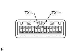
Measure the resistance according to the value(s) in the table below.
- Standard Resistance:
Tester Connection
| Condition
| Specified Condition
|
8 (TX1-) - 7 (TX1+)
| Always
| 60 to 80 Ω
|
| | REPLACE RADIO AND DISPLAY RECEIVER ASSEMBLY (Click here) |
|
|
| 6.CHECK HARNESS AND CONNECTOR (RADIO AND DISPLAY RECEIVER ASSEMBLY - STEREO COMPONENT AMPLIFIER ASSEMBLY) |
Disconnect the F124 radio and display receiver assembly connector.
Disconnect the F18 stereo component amplifier assembly connector.
Measure the resistance according to the value(s) in the table below.
- Standard Resistance:
Tester Connection
| Condition
| Specified Condition
|
F124-7 (TX1+) - F18-8 (TX+)
| Always
| Below 1 Ω
|
F124-8 (TX1-) - F18-7 (TX-)
| Always
| Below 1 Ω
|
F124-7 (TX1+) - Body ground
| Always
| 10 kΩ or higher
|
F124-8 (TX1-) - Body ground
| Always
| 10 kΩ or higher
|
| | REPAIR OR REPLACE HARNESS OR CONNECTOR |
|
|
| 7.CHECK STEREO COMPONENT AMPLIFIER ASSEMBLY |
Replace the stereo component amplifier assembly with a known good one (Click here).
Clear the DTCs (Click here).
Check for DTCs (Click here).
- OK:
- No DTCs are output.
| | REPLACE RADIO AND DISPLAY RECEIVER ASSEMBLY (Click here) |
|
|
| OK |
|
|
|
| END (STEREO COMPONENT AMPLIFIER ASSEMBLY IS DEFECTIVE) |
|