Dtc B15D3 Stereo Component Amplifier Disconnected
DESCRIPTION
WIRING DIAGRAM
INSPECTION PROCEDURE
CHECK OPTIONAL COMPONENTS (INCLUDING ASSOCIATED WIRING)
REMOVE OPTIONAL COMPONENTS (INCLUDING ASSOCIATED WIRING)
CLEAR DTC
CHECK DTC
CHECK HARNESS AND CONNECTOR (STEREO COMPONENT AMPLIFIER ASSEMBLY - BATTERY AND BODY GROUND)
CHECK HARNESS AND CONNECTOR (MULTI-MEDIA MODULE RECEIVER ASSEMBLY - STEREO COMPONENT AMPLIFIER ASSEMBLY)
REPLACE STEREO COMPONENT AMPLIFIER ASSEMBLY
CLEAR DTC
CHECK DTC
CHECK HARNESS AND CONNECTOR (STEREO COMPONENT AMPLIFIER ASSEMBLY - MULTI-MEDIA MODULE RECEIVER AND TELEVISION DISPLAY)
REPLACE STEREO COMPONENT AMPLIFIER ASSEMBLY
CLEAR DTC
CHECK DTC
DTC B15D3 Stereo Component Amplifier Disconnected |
DESCRIPTION
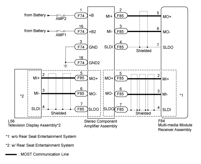
The multi-media module receiver assembly and stereo component amplifier assembly are connected by the MOST communication line.When a MOST communication error occurs between the multi-media module receiver assembly and stereo component amplifier assembly, these DTCs will be stored.DTC Code
| DTC Detection Condition
| Trouble Area
|
B15D3
| A device that is listed in the MOST network connected device record of the master unit is missing.
| - Stereo component amplifier assembly power source circuit
- MOST circuit between multi-media module receiver assembly and stereo component amplifier assembly
- Stereo component amplifier assembly
- Multi-media module receiver assembly
|
- HINT:
- For the MOST network, the multi-media module receiver assembly is the master unit.
WIRING DIAGRAM
INSPECTION PROCEDURE
- NOTICE:
- Inspect the fuses for circuits related to this system before performing the following inspection procedure.
| 1.CHECK OPTIONAL COMPONENTS (INCLUDING ASSOCIATED WIRING) |
Check for optional components.
Check that optional components (including associated wiring) which generate radio waves are not installed.
ResultResult
| Proceed to
|
Optional components (including associated wiring) are installed.
| A
|
Optional components (including associated wiring) are not installed.
| B
|
- HINT:
- Electrical noise from radio waves generated by optional components or the wiring for those components may affect MOST communication.
- This DTC may be stored when a MOST communication error occurs due to electrical noise.
| 2.REMOVE OPTIONAL COMPONENTS (INCLUDING ASSOCIATED WIRING) |
Remove optional components (including associated wiring).
- NOTICE:
- Do not remove optional components or associated wiring without the permission of the customer.
Clear the DTCs (Click here).
Recheck for DTCs and check if the same DTC is output again (Click here).
- OK:
- No DTCs are output.
| OK |
|
|
|
| END (COMMUNICATION MALFUNCTION DUE TO NOISE) |
|
| 5.CHECK HARNESS AND CONNECTOR (STEREO COMPONENT AMPLIFIER ASSEMBLY - BATTERY AND BODY GROUND) |
Disconnect the stereo component amplifier assembly connector.
Measure the resistance according to the value(s) in the table below.
- Standard Resistance:
Tester Connection
| Condition
| Specified Condition
|
F74-3 (GND) - Body ground
| Always
| Below 1 Ω
|
F74-18 (GND2) - Body ground
| Always
| Below 1 Ω
|
Measure the voltage according to the value(s) in the table below.
- Standard Voltage:
Tester Connection
| Condition
| Specified Condition
|
F74-1 (+B) - F74-3 (GND)
| Always
| 11 to 14 V
|
F74-16 (+B2) - F74-3 (GND)
| Always
| 11 to 14 V
|
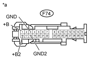
Text in Illustration*a
| Front view of wire harness connector
(to Stereo Component Amplifier Assembly)
|
ResultResult
| Proceed to
|
OK (w/o Rear Seat Entertainment System)
| A
|
OK (w/ Rear Seat Entertainment System)
| B
|
NG
| C
|
| |
|
| | REPAIR OR REPLACE HARNESS OR CONNECTOR |
|
|
| 6.CHECK HARNESS AND CONNECTOR (MULTI-MEDIA MODULE RECEIVER ASSEMBLY - STEREO COMPONENT AMPLIFIER ASSEMBLY) |
Disconnect the F84 multi-media module receiver assembly connector.
Disconnect the F85 stereo component amplifier assembly connector.
Measure the resistance according to the value(s) in the table below.
- Standard Resistance:
Tester Connection
| Condition
| Specified Condition
|
F84-2 (MI+) - F85-5 (MO+)
| Always
| Below 1 Ω
|
F84-3 (MI-) - F85-6 (MO-)
| Always
| Below 1 Ω
|
F84-4 (SLDI) - F85-7 (SLDO)
| Always
| Below 1 Ω
|
F84-5 (MO+) - F85-2 (MI+)
| Always
| Below 1 Ω
|
F84-6 (MO-) - F85-3 (MI-)
| Always
| Below 1 Ω
|
F84-7 (SLDO) - F85-4 (SLDI)
| Always
| Below 1 Ω
|
F84-2 (MI+) - Body ground
| Always
| 10 kΩ or higher
|
F84-3 (MI-) - Body ground
| Always
| 10 kΩ or higher
|
F84-4 (SLDI) - Body ground
| Always
| 10 kΩ or higher
|
F84-5 (MO+) - Body ground
| Always
| 10 kΩ or higher
|
F84-6 (MO-) - Body ground
| Always
| 10 kΩ or higher
|
F84-7 (SLDO) - Body ground
| Always
| 10 kΩ or higher
|
| | REPAIR OR REPLACE HARNESS OR CONNECTOR |
|
|
| 7.REPLACE STEREO COMPONENT AMPLIFIER ASSEMBLY |
Replace the stereo component amplifier assembly with a new or normally functioning one (Click here).
Clear the DTCs (Click here).
Recheck for DTCs and check if the same DTC is output again (Click here).
- OK:
- No DTCs are output
| | REPLACE MULTI-MEDIA MODULE RECEIVER ASSEMBLY (Click here) |
|
|
| OK |
|
|
|
| END (STEREO COMPONENT AMPLIFIER ASSEMBLY IS DEFECTIVE) |
|
| 10.CHECK HARNESS AND CONNECTOR (STEREO COMPONENT AMPLIFIER ASSEMBLY - MULTI-MEDIA MODULE RECEIVER AND TELEVISION DISPLAY) |
Disconnect the F84 multi-media module receiver assembly connector.
Disconnect the F85 stereo component amplifier assembly connector.
Disconnect the L56 television assembly connector.
Measure the resistance according to the value(s) in the table below.
- Standard Resistance:
Tester Connection
| Condition
| Specified Condition
|
F84-5 (MO+) - F85-2 (MI+)
| Always
| Below 1 Ω
|
F84-6 (MO-) - F85-3 (MI-)
| Always
| Below 1 Ω
|
F84-7 (SLDO) - F85-4 (SLDI)
| Always
| Below 1 Ω
|
F85-5 (MO+) - L56-2 (MI+)
| Always
| Below 1 Ω
|
F85-6 (MO-) - L56-3 (MI-)
| Always
| Below 1 Ω
|
F85-7 (SLDO) - L56-4 (SLDI)
| Always
| Below 1 Ω
|
F85-2 (MI+) - Body ground
| Always
| 10 kΩ or higher
|
F85-3 (MI-) - Body ground
| Always
| 10 kΩ or higher
|
F85-4 (SLDI) - Body ground
| Always
| 10 kΩ or higher
|
F85-5 (MO+) - Body ground
| Always
| 10 kΩ or higher
|
F85-6 (MO-) - Body ground
| Always
| 10 kΩ or higher
|
F85-7 (SLDO) - Body ground
| Always
| 10 kΩ or higher
|
| | REPAIR OR REPLACE HARNESS OR CONNECTOR |
|
|
| 11.REPLACE STEREO COMPONENT AMPLIFIER ASSEMBLY |
Replace the stereo component amplifier assembly with a new or normally functioning one (Click here).
Clear the DTCs (Click here).
Recheck for DTCs and check if the same DTC is output again (Click here).
| | REPLACE MULTI-MEDIA MODULE RECEIVER ASSEMBLY (Click here) |
|
|
| OK |
|
|
|
| END (STEREO COMPONENT AMPLIFIER ASSEMBLY IS DEFECTIVE) |
|