Drivetrain. Land Cruiser. Urj200, 202 Grj200 Vdj200
REMOVE STABILIZER CONTROL VALVE PROTECTOR (w/ KDSS)
OPEN STABILIZER CONTROL WITH ACCUMULATOR HOUSING SHUTTER VALVE (w/ KDSS)
DISCONNECT CABLE FROM NEGATIVE BATTERY TERMINAL
DISCONNECT FRONT SPEED SENSOR LH
REMOVE FRONT AXLE HUB SUB-ASSEMBLY LH
DISCONNECT TIE ROD END SUB-ASSEMBLY LH
DISCONNECT FRONT LOWER BALL JOINT ATTACHMENT LH
REMOVE STEERING KNUCKLE LH
REMOVE STEERING KNUCKLE OIL SEAL LH
Steering Knuckle -- Removal |
- HINT:
- Use the same procedures for the LH side and RH side.
- The procedures listed below are for the LH side.
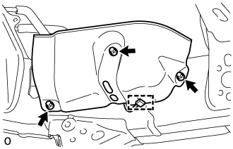
| 1. REMOVE STABILIZER CONTROL VALVE PROTECTOR (w/ KDSS) |
Detach the clamp, and disconnect the connector from the protector.
Remove the 3 bolts and protector.
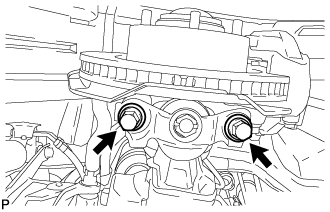
| 2. OPEN STABILIZER CONTROL WITH ACCUMULATOR HOUSING SHUTTER VALVE (w/ KDSS) |
Using a 5 mm hexagon socket wrench, loosen the lower and upper chamber shutter valves of the stabilizer control with accumulator housing 2.0 to 3.5 turns.
- NOTICE:
- When loosening a shutter valve, make sure that the end protrudes 2 to 3.5 mm (0.0787 to 0.137 in.) from the surface of the block, and do not turn the shutter valve any further.
- Do not remove the shutter valves.
| 3. DISCONNECT CABLE FROM NEGATIVE BATTERY TERMINAL |
- CAUTION:
- Wait at least 90 seconds after disconnecting the cable from the negative (-) battery terminal to disable the SRS system.
- NOTICE:
- When disconnecting the cable, some systems need to be initialized after the cable is reconnected (Click here).
| 4. DISCONNECT FRONT SPEED SENSOR LH |
Remove the bolt, skid control sensor clamp and sensor wire.
Using a 5 mm hexagon socket, remove the bolt and speed sensor from the knuckle.
- NOTICE:
- Pull out the sensor while trying as much as possible not to rotate it.
| 5. REMOVE FRONT AXLE HUB SUB-ASSEMBLY LH |
Remove the front axle hub (Click here).
| 6. DISCONNECT TIE ROD END SUB-ASSEMBLY LH |
Remove the cotter pin and nut.
Using SST, disconnect the tie rod end LH from the steering knuckle.
- SST
- 09610-20012
- NOTICE:
- Do not damage the front disc brake dust cover.
- Do not damage the ball joint dust cover.
- Do not damage the steering knuckle.
| 7. DISCONNECT FRONT LOWER BALL JOINT ATTACHMENT LH |
Remove the 2 bolts and disconnect the attachment from the steering knuckle.
| 8. REMOVE STEERING KNUCKLE LH |
Support the front suspension lower arm LH with a jack.
Remove the clip and nut.
Using SST, disconnect the upper ball joint from the steering knuckle.
- SST
- 09628-62011
- NOTICE:
- Do not damage the ball joint dust cover.
Remove the steering knuckle.
| 9. REMOVE STEERING KNUCKLE OIL SEAL LH |
Using a screwdriver and hammer, tap out the oil seal.