Dtc P2431 Secondary Air Injection System Air Flow / Pressure Sensor Circuit Range / Performance Bank1
DESCRIPTION
MONITOR DESCRIPTION
CONFIRMATION DRIVING PATTERN
WIRING DIAGRAM
INSPECTION PROCEDURE
CHECK HARNESS AND CONNECTOR (PRESSURE SENSOR - ECM)
CHECK TERMINAL VOLTAGE (VC OF AIR SWITCHING VALVE)
REPLACE AIR SWITCHING VALVE ASSEMBLY
CHECK WHETHER DTC OUTPUT RECURS
DTC P2431 Secondary Air Injection System Air Flow / Pressure Sensor Circuit Range / Performance Bank1 |
DTC P2432 Secondary Air Injection System Air Flow / Pressure Sensor Circuit Low Bank1 |
DTC P2433 Secondary Air Injection System Air Flow / Pressure Sensor Circuit High Bank1 |
DTC P2436 Secondary Air Injection System Air Flow / Pressure Sensor Circuit Range / Performance Bank 2 |
DTC P2437 Secondary Air Injection System Air Flow / Pressure Sensor Circuit Low Bank 2 |
DTC P2438 Secondary Air Injection System Air Flow / Pressure Sensor Circuit High Bank 2 |
DESCRIPTION
Refer to DTC P0412 (Click here).Refer to DTC P0416 (Click here).DTC No.
| DTC Detection Condition
| Trouble Area
|
P2431
P2436
| Pressure sensor indicates a value below 45.6 kPa (342 mmHg), or higher than 135 kPa (1013 mmHg) (2 trip detection logic).
| - Pressure sensor
- Open or short in pressure sensor circuit
- ECM
|
P2432
P2437
| While the engine is running, the voltage output of the pressure sensor is below 0.5 V (1 trip detection logic).
| - Pressure sensor
- Open or short in pressure sensor circuit
- ECM
|
P2433
P2438
| While the engine is running, the voltage output of the pressure sensor is higher than 4.5 V (1 trip detection logic).
| - Pressure sensor
- Open or short in pressure sensor circuit
- ECM
|
MONITOR DESCRIPTION
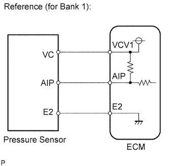 The ECM monitors the pressure in the secondary air passage using the pressure sensor located on the air switching valve in the secondary air injection system. Using this pressure value, the ECM determines whether the secondary air injection system is malfunctioning or not.If there is a defect in the sensor or the sensor circuit, the voltage level deviates from the normal operating range. The ECM interprets this deviation as a malfunction in the pressure sensor or circuit and stores a DTC.
CONFIRMATION DRIVING PATTERN
- NOTICE:
- This Secondary Air Injection Check only allows technicians to operate the Secondary Air Injection system for a maximum of 5 seconds. Furthermore, the check can only be performed up to 4 times per trip. If the test is repeated, intervals of at least 30 seconds are required between checks. While Secondary Air Injection system operation using the GTS is prohibited, the GTS display indicates the prohibition (WAIT or ERROR). If ERROR is displayed on the GTS during the test, stop the engine for 10 minutes, and then try again.
- Performing Secondary Air Injection Check repeatedly may cause damage to the secondary air injection system. If it is necessary to repeat the check, leave an interval of several minutes between System Check operations to prevent the system from overheating.
- When performing the Secondary Air Injection Check operation after the battery cable has been reconnected, wait for 7 minutes with the engine switch turned on (IG) or the engine running.
- Turn the engine switch off when the Secondary Air Injection Check operation finishes.
- Start the engine and warm it up.
- Turn the engine switch off.
- Connect the GTS to the DLC3.
- Turn the engine switch on (IG).
- Turn the GTS on.
- Clear DTCs (even if no DTCs are stored, perform the clear DTC operation) (Click here).
- Turn the engine switch off and wait for at least 30 seconds.
- Turn the engine switch on (IG) and turn the GTS on.
- Enter the following menus: Powertrain / Engine and ECT / Utility / Secondary Air Injection Check / Automatic Mode.
- Start the engine after the GTS initialization is finished.
- Perform the System Check operation by pressing ENTER (Next).
- Perform the following to confirm the Secondary Air Injection system pending codes: Press ENTER (Exit).
- Check for pending DTCs.
- OK:
- No pending DTC is output.
- After "Secondary Air Injection Check" is completed, check for All Readiness by entering the following menus: Powertrain / Engine and ECT / Utility / All Readiness.
- Input the DTC: P2431, P2432, P2433, P2436, P2437 or P2438.
- Check the DTC judgment result.
GTS Display
| Description
|
NORMAL
| - DTC judgment completed
- System normal
|
ABNORMAL
| - DTC judgment completed
- System abnormal
|
INCOMPLETE
| - DTC judgment not completed
- Perform driving pattern after confirming DTC enabling conditions
|
N/A
| - Unable to perform DTC judgment
- Number of DTCs which do not fulfill DTC preconditions has reached ECU memory limit
|
- HINT:
- If the judgment result shows NORMAL, the system is normal.
- If the judgment result shows ABNORMAL, the system has a malfunction.
- Turn the engine switch off.
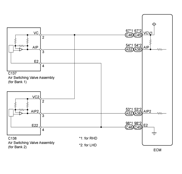
WIRING DIAGRAM
INSPECTION PROCEDURE
- HINT:
- Refer to "Data List / Active Test" [Air Pump Pressure (Absolute) and Air Pump2 Pressure (Absolute)] (Click here).
- Read freeze frame data using the GTS. Freeze frame data records the engine condition when malfunctions are detected. When troubleshooting, freeze frame data can help determine if the vehicle was moving or stationary, if the engine was warmed up or not, if the air-fuel ratio was lean or rich, and other data from the time the malfunction occurred.
- Bank 1 refers to the bank that includes the No. 1 cylinder*.
*: The No. 1 cylinder is the cylinder which is farthest from the transmission.
- Bank 2 refers to the bank that does not include the No. 1 cylinder.
| 1.CHECK HARNESS AND CONNECTOR (PRESSURE SENSOR - ECM) |
Disconnect the air switching valve connector.
Disconnect the ECM connectors.
Measure the resistance according to the value(s) in the table below.
- Standard Resistance:
for RHDTester Connection
| Condition
| Specified Condition
|
C137-3 (AIP) - A52-54 (AIP)
| Always
| Below 1 Ω
|
C137-2 (VC) - C46-67 (VCV1)
| Always
| Below 1 Ω
|
C137-4 (E2) - C46-98 (E2)
| Always
| Below 1 Ω
|
C138-3 (AIP2) - A52-53 (AIP2)
| Always
| Below 1 Ω
|
C138-2 (VC2) - C46-67 (VCV1)
| Always
| Below 1 Ω
|
C138-4 (E22) - C46-98 (E2)
| Always
| Below 1 Ω
|
C137-3 (AIP) or A52-54 (AIP) - Body ground
| Always
| 10 kΩ or higher
|
C137-2 (VC) or C46-67 (VCV1) - Body ground
| Always
| 10 kΩ or higher
|
C138-3 (AIP2) or A52-53 (AIP2) - Body ground
| Always
| 10 kΩ or higher
|
C138-2 (VC2) or C46-67 (VCV1) - Body ground
| Always
| 10 kΩ or higher
|
- Standard Resistance:
for LHDTester Connection
| Condition
| Specified Condition
|
C137-3 (AIP) - A38-54 (AIP)
| Always
| Below 1 Ω
|
C137-2 (VC) - C45-67 (VCV1)
| Always
| Below 1 Ω
|
C137-4 (E2) - C45-98 (E2)
| Always
| Below 1 Ω
|
C138-3 (AIP2) - A38-53 (AIP2)
| Always
| Below 1 Ω
|
C138-2 (VC2) - C45-67 (VCV1)
| Always
| Below 1 Ω
|
C138-4 (E22) - C45-98 (E2)
| Always
| Below 1 Ω
|
C137-3 (AIP) or A38-54 (AIP) - Body ground
| Always
| 10 kΩ or higher
|
C137-2 (VC) or C45-67 (VCV1) - Body ground
| Always
| 10 kΩ or higher
|
C138-3 (AIP2) or A38-53 (AIP2) - Body ground
| Always
| 10 kΩ or higher
|
C138-2 (VC2) or C45-67 (VCV1) - Body ground
| Always
| 10 kΩ or higher
|
| | REPAIR OR REPLACE HARNESS OR CONNECTOR |
|
|
| 2.CHECK TERMINAL VOLTAGE (VC OF AIR SWITCHING VALVE) |
Disconnect the air switching valve connector.
Turn the engine switch on (IG).
Measure the voltage according to the value(s) in the table below.
- Standard Resistance:
Tester Connection
| Condition
| Specified Condition
|
C137-2 (VC) - C137-4 (E2)
| Engine switch on (IG)
| 4.5 to 5.5 V
|
C138-2 (VC2) - C138-4 (E22)
| Engine switch on (IG)
| 4.5 to 5.5 V
|
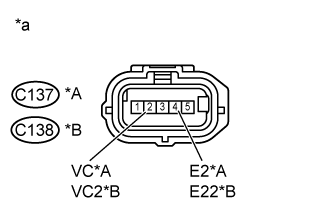
Text in Illustration*A
| Bank 1
|
*B
| Bank 2
|
*a
| Front view of wire harness connector
(to Air Switching Valve Assembly)
|
| 3.REPLACE AIR SWITCHING VALVE ASSEMBLY |
Replace the air switching valve assembly.
- HINT:
- Replace the air switching valve assembly for bank 1 (Click here).
- Replace the air switching valve assembly for bank 2 (Click here).
| 4.CHECK WHETHER DTC OUTPUT RECURS |
Perform the Confirmation Driving Pattern.
ResultDisplay (DTC Output)
| Proceed to
|
NORMAL
(No DTC output)
| A
|
ABNORMAL
(P2431, P2432, P2433, P2436, P2437 or P2438 output)
| B
|