Ecd System (W/ Dpf) -- Data List / Active Test |
| DATA LIST |
- HINT:
- Using the GTS to read the Data List allows the values or states of switches, sensors, actuators and other items to be read without removing any parts. This non-intrusive inspection can be very useful because intermittent conditions or signals may be discovered before parts or wiring is disturbed. Reading the Data List information early in troubleshooting is one way to save diagnostic time.
- NOTICE:
- In the table below, the values listed under "Normal Condition" are reference values. Do not depend solely on these reference values when deciding whether a part is faulty or not.
Warm up the engine.
Turn the engine switch off.
Connect the GTS to the DLC3.
Turn the engine switch on (IG).
Start the engine.
Turn the GTS on.
Enter the following menus: Engine and ECT / Data List.
- HINT:
- To display the list box, press the pull down menu button next to "Primary". Then select a measurement group.
- When you select a measurement group, the ECU data belonging to that group is displayed.
- Measurement Group List / Description
- All Data / All data
- Primary / -
- Diesel General / General diesel data
- Common Rail / Diesel common rail system related data
- Common Rail (All) / Diesel common rail system related data (All data)
- Diesel EGR / Diesel EGR system related data
- Diesel Throttle / Diesel throttle system related data
- VN Turbo / VN turbo related data
- Diesel Exhaust / After treatment control system related data
- Diesel Starting / "Difficult to start" related data
- Diesel Rough / "Rough idle" related data
- Diesel Lack of Power / "Lack of power" related data
- Diesel Knocking / "Knocking" related data
- Diesel Black Smoke / "Black smoke" related data
- Compression / Data used during "Check the Cylinder Compression" Active Test
- A/T / Automatic transaxle system related data
- Vehicle Information / Vehicle information
Check the values by referring to the table below.
- NOTICE:
- Normal Condition: If no idling conditions are specified, the shift lever should be in the neutral position, the A/C switch and all accessory switches should be off, and PM forced regeneration should not be being performed.
- "Result of real-vehicle check" is the assessment of one vehicle. Use it only for reference.
| Engine Control |
| Tester Display | Measurement Item/Range | Normal Condition | Type | Cause of Out of Range |
| Calculate Load | Load calculated by ECM/ Min.: 0%, Max.: 100% |
| Calculated by ECM | Malfunction in which turbo pressure or Mass Air Flow decreases |
Results of real-vehicle check:
| ||||
| Diagnostic Note: Calculated load = (Final injection volume / max. injection volume at current engine speed) x 100. | ||||
| Tester Display | Measurement Item/Range | Normal Condition | Type | Cause of Out of Range |
| MAF | Airflow rate from mass air flow meter/ Min.: 0 gm/sec, Max.: 400 gm/sec |
| Sensor output (mass air flow meter) |
|
Results of real-vehicle check:
| ||||
| Symptoms when out of range: Rough idling | ||||
Diagnostic Note:
| ||||
| Tester Display | Measurement Item/Range | Normal Condition | Type | Cause of Out of Range |
| Engine Speed | Engine speed/ Min.: 0 rpm, Max.: 6000 rpm | 550 to 650 rpm: Idling with warm engine and PM forced regeneration not being performed
| Sensor output (crankshaft position sensor) |
|
| Diagnostic Note: When the crankshaft position sensor is malfunctioning, "Engine Speed" is approximately 0 or varies greatly from the actual engine speed. | ||||
| Tester Display | Measurement Item/Range | Normal Condition | Type | Cause of Out of Range |
| Target Idle Engine Speed | Target Idling Engine Speed/ Min.: 0 rpm, Max.: 10000 rpm | - | Target idling speed (ECM calculated value) | - |
Diagnostic Note:
| ||||
| Tester Display | Measurement Item/Range | Normal Condition | Type | Cause of Out of Range |
| MAP | Absolute pressure inside intake manifold/ Min.: 0 kPa, Max.: 320 kPa |
| Sensor output (manifold absolute pressure sensor) |
|
Results of real-vehicle check:
| ||||
| Symptoms when out of range: Lack of power | ||||
Diagnostic Note:
| ||||
| Tester Display | Measurement Item/Range | Normal Condition | Type | Cause of Out of Range |
| Vehicle Speed | Vehicle speed/ Min.: 0 km/h, Max.: 255 km/h | Actual vehicle speed | Sensor output (speed sensor) |
|
| Tester Display | Measurement Item/Range | Normal Condition | Type | Cause of Out of Range |
| Coolant Temp | Engine coolant temperature/ Min.: -40°C, Max.: 140°C | After warming up engine: 70 to 90°C (158 to 194°F) | Sensor output (engine coolant temperature sensor) |
|
| Symptoms when out of range: Difficulty starting when engine is cold, rough idle, black smoke, lack of power | ||||
Diagnostic Note:
| ||||
| Tester Display | Measurement Item/Range | Normal Condition | Type | Cause of Out of Range |
| Intake Air | Intake air temperature/ Min.: -40°C, Max.: 140°C | Equivalent to temperature at location of mass air flow meter | Sensor output (intake air temperature sensor (built into mass air flow meter)) | Intake air temperature sensor |
Diagnostic Note:
| ||||
| Tester Display | Measurement Item/Range | Normal Condition | Type | Cause of Out of Range |
| Initial Engine Coolant Temp | Initial engine coolant temperature/ Min.: -40°C, Max.: 120°C | Engine coolant temperature when engine started | Sensor output when engine started | - |
| Diagnostic Note: For freeze frame data, this tells whether the malfunction happened at a cold start or with a warm engine. | ||||
| Tester Display | Measurement Item/Range | Normal Condition | Type | Cause of Out of Range |
| Initial Intake Air Temp | Initial intake air temperature/ Min.: -40°C, Max.: 120°C | Intake air temperature when engine started | Sensor output when engine started | - |
| Tester Display | Measurement Item/Range | Normal Condition | Type | Cause of Out of Range |
| Intake Air Temp (Turbo) | Intake air temperature after intercooler/ Min.: -40°C, Max.: 190°C | 70°C (158°F) or less | Sensor output (intake air temperature sensor after intercooler) | Decreased cooling efficiency of intercooler (contamination, clogging) |
Diagnostic Note:
| ||||
| Tester Display | Measurement Item/Range | Normal Condition | Type | Cause of Out of Range |
| Alternate Duty Ratio | Alternator generation duty ratio/ Min.: 0%, Max.: 100% |
| Duty value from ALT terminal |
|
| Results of real-vehicle check: Idling (no electrical load) (warm up the engine): 40% (2 minutes after starting the vehicle) | ||||
Diagnostic Note:
| ||||
| Tester Display | Measurement Item/Range | Normal Condition | Type | Cause of Out of Range |
| Viscous Heater Stop Request | Viscous heater stop request/ ON or OFF | ON: Viscous heater stop requested | - | - |
| Tester Display | Measurement Item/Range | Normal Condition | Type | Cause of Out of Range |
| A/C Signal | A/C (Air Conditioner) signal/ ON or OFF | ON: A/C on | A/C operation signal output from A/C amplifier
|
|
| Symptoms when out of range: OFF malfunction (OFF even when A/C switch is turned on):
| ||||
| Tester Display | Measurement Item/Range | Normal Condition | Type | Cause of Out of Range |
| Stop Light Switch | Stop light switch/ ON or OFF |
| Switch output (stop light switch) |
|
| Symptoms when out of range: Stop light switch malfunction DTC P0504 is stored | ||||
| Diagnostic Note: Stop light switch (STP) operation condition:
| ||||
| Tester Display | Measurement Item/Range | Normal Condition | Type | Cause of Out of Range |
| Battery Voltage | Battery voltage/ Min.: 0 V, Max.: 15 V | 11 to 14 V | - | - |
Results of real-vehicle check:
| ||||
| Symptoms when out of range: If 5 V or less, starting becomes difficult | ||||
| Diagnostic Note: If 11 V or less, characteristics of some electrical components change. | ||||
| Tester Display | Measurement Item/Range | Normal Condition | Type | Cause of Out of Range |
| Atmosphere Pressure | Atmospheric pressure value/ Min.: 50 kPa, Max.: 120 kPa | Actual atmospheric pressure | Sensor output (atmospheric pressure sensor (built into ECM)) | Atmospheric pressure sensor itself has failed (atmospheric pressure sensor is inside the ECM) |
Diagnostic Note:
| ||||
| Tester Display | Measurement Item/Range | Normal Condition | Type | Cause of Out of Range |
| ACT VSV | A/C cut status/ ON or OFF | - | - | - |
| Diagnostic Note: "Control the A/C Cut Signal" Active Test support data. | ||||
| Tester Display | Measurement Item/Range | Normal Condition | Type | Cause of Out of Range |
| TC and TE1 | TC and TE1 connection status/ ON or OFF | - | - | - |
| Diagnostic Note: When the "Connect the TC and TE1" Active Test is performed, the system behaves as if TC and CG were connected. | ||||
| Tester Display | Measurement Item/Range | Normal Condition | Type | Cause of Out of Range |
| # Codes (Include History) | Number of codes/ Min.: 0, Max.: 255 | - | - | - |
| Diagnostic Note: Number of DTCs appearing at least once during the last 40 times the vehicle was warmed up. | ||||
| Tester Display | Measurement Item/Range | Normal Condition | Type | Cause of Out of Range |
| Check Mode | Check mode status/ ON or OFF | ON: Check mode on | - | - |
| Diagnostic Note: Check Mode: The mode in which certain DTCs can be detected more easily and with higher sensitivity. | ||||
| Tester Display | Measurement Item/Range | Normal Condition | Type | Cause of Out of Range |
| MIL | MIL status/ ON or OFF | OFF: MIL off | - | - |
| Tester Display | Measurement Item/Range | Normal Condition | Type | Cause of Out of Range |
| MIL ON Run Distance | Distance traveled with MIL on/ Min.: 0 km, Max.: 65535 km | Distance traveled after DTC stored | Result of ECU calculations (using the vehicle speed) | - |
Diagnostic Note:
| ||||
| Tester Display | Measurement Item/Range | Normal Condition | Type | Cause of Out of Range |
| Running Time from MIL ON | Running time after MIL turns on/ Min.: 0 min., Max.: 65535 min. | Running time after MIL turns on | - | - |
Diagnostic Note:
| ||||
| Tester Display | Measurement Item/Range | Normal Condition | Type | Cause of Out of Range |
| Engine Run Time | Engine run time/ Min.: 0 sec., Max.: 65535 sec. | Time after the engine switch turned on (IG) | Result of ECU calculations (using the engine speed) | - |
| Diagnostic Note: Time passed since the engine switch was turned on (IG). | ||||
| Tester Display | Measurement Item/Range | Normal Condition | Type | Cause of Out of Range |
| Time after DTC Cleared | Time after DTC cleared/ Min.: 0 min., Max.: 65535 min. | Time after DTCs cleared | - | - |
| Diagnostic Note: Time elapsed since the DTCs were cleared (or shipment from the factory). | ||||
| Tester Display | Measurement Item/Range | Normal Condition | Type | Cause of Out of Range |
| Distance from DTC Cleared | Distance driven after DTC cleared/ Min.: 0 km, Max.: 65535 km | Distance driven after DTCs cleared | - | - |
Diagnostic Note:
| ||||
| Tester Display | Measurement Item/Range | Normal Condition | Type | Cause of Out of Range |
| Warmup Cycle Cleared DTC | Warmup cycles after DTC cleared/ Min.: 0, Max.: 255 | - | - | - |
Diagnostic Note:
| ||||
| Tester Display | Measurement Item/Range | Normal Condition | Type | Cause of Out of Range |
| OBD Requirements | Identifying OBD requirement | - | - | - |
| Diagnostic Note: Euro-OBD | ||||
| Tester Display | Measurement Item/Range | Normal Condition | Type | Cause of Out of Range |
| Number of Emission DTC | Number of emissions-related DTCs | - | - | - |
| Tester Display | Measurement Item/Range | Normal Condition | Type | Cause of Out of Range |
| Power Steering Signal | Power steering switch status: ON or OFF | ON: Power steering operation | Switch output (power steering switch) |
|
| Symptoms when out of range: OFF malfunction (OFF during power steering operation): Engine speed decreases temporarily when power steering is operating | ||||
| Tester Display | Measurement Item/Range | Normal Condition | Type | Cause of Out of Range |
| ACC Relay | ACC relay status ON or OFF | ON: ACC relay ON | - | - |
| Tester Display | Measurement Item/Range | Normal Condition | Type | Cause of Out of Range |
| Transfer L4 | L4 status of the transfer/ ON or OFF | ON: 4WD control switch in 4L position | - | - |
| Tester Display | Measurement Item/Range | Normal Condition | Type | Cause of Out of Range |
| Idle Up Signal | Status of the idle up signal/ ON or OFF | - | - | - |
| Tester Display | Measurement Item/Range | Normal Condition | Type | Cause of Out of Range |
| TC Terminal | TC terminal status/ ON or OFF | - | - | - |
| Tester Display | Measurement Item/Range | Normal Condition | Type | Cause of Out of Range |
| Dist Batt Cable Disconnect | Distance driven after battery cable disconnected/ Min.: 0 km, Max.: 65535 km | Total distance vehicle driven after battery cable disconnected | - | - |
| Tester Display | Measurement Item/Range | Normal Condition | Type | Cause of Out of Range |
| IG OFF Elapsed Time | Time after engine switch turned off/ Min.: 0 min, Max.: 655350 min | Cumulative time after engine switch turned off | - | - |
| Tester Display | Measurement Item/Range | Normal Condition | Type | Cause of Out of Range |
| Minimum Engine Speed | Minimum engine speed/ Min.: 0 rpm, Max.: 51199 rpm | - | - | - |
| Tester Display | Measurement Item/Range | Normal Condition | Type | Cause of Out of Range |
| ACM Inhibit | VSV for engine mount status: ON or OFF | - | - | - |
Diagnostic Note:
| ||||
| Tester Display | Measurement Item/Range | Normal Condition | Type | Cause of Out of Range |
| Accel Position | Accelerator position status/ Min.: 0%, Max.: 100% |
|
| - |
Results of real-vehicle check:
| ||||
Diagnostic Note:
| ||||
- HINT:
- Accel Sens. No.1 Volt % and Accel Sens. No.2 Volt % express the value obtained by dividing the output voltage from the accelerator pedal position sensor by 5. This is used only for diagnosing malfunctions in the accelerator pedal position sensor. Under normal conditions, it is sufficient to only check the final accelerator opening angle value "Accel Position".
| Tester Display | Measurement Item/Range | Normal Condition | Type | Cause of Out of Range |
| Accel Sens. No.1 Volt % | Accelerator position No. 1/ Min.: 0%, Max.: 100% |
| Sensor output (Accelerator pedal position sensor) | - |
| Diagnostic Note: Read value with engine switch on (IG) (do not start engine). | ||||
| Tester Display | Measurement Item/Range | Normal Condition | Type | Cause of Out of Range |
| Accel Sens. No.2 Volt % | Accelerator position No. 2/ Min.: 0%, Max.: 100% |
| Sensor output (Accelerator pedal position sensor) | - |
| Diagnostic Note: Read value with engine switch on (IG) (do not start engine). | ||||
| Compression |
| Tester Display | Measurement Item/Range | Normal Condition | Type | Cause of Out of Range |
| Engine Speed of Cyl #1 Engine Speed of Cyl #2 Engine Speed of Cyl #3 Engine Speed of Cyl #4 Engine Speed of Cyl #5 Engine Speed of Cyl #6 Engine Speed of Cyl #7 Engine Speed of Cyl #8 | Engine speed for No. 1 to No. 8 cylinder/ Min.: 0 rpm, Max.: 51199 rpm | Engine speeds of all cylinders almost same | - | Compression goes down |
| Symptoms when out of range: When the engine speeds of all cylinders are not equal, idling will be rough. | ||||
Diagnostic Note:
| ||||
| Tester Display | Measurement Item/Range | Normal Condition | Type | Cause of Out of Range |
| Av Engine Speed of All Cyl | Engine speed for all cylinders/ Min.: 0 rpm, Max.: 51199 rpm | - | - | - |
Diagnostic Note:
| ||||
| Vehicle Information |
| Tester Display | Measurement Item/Range | Normal Condition | Type | Cause of Out of Range |
| Model Code | Model code | - | - | - |
| Diagnostic Note: Identifying model code: VDJ200 | ||||
| Tester Display | Measurement Item/Range | Normal Condition | Type | Cause of Out of Range |
| Engine Type | Engine type | - | - | - |
| Diagnostic Note: Identifying engine type: 1VDFTV | ||||
| Tester Display | Measurement Item/Range | Normal Condition | Type | Cause of Out of Range |
| Cylinder Number | Cylinder number/ Min.: 0, Max.: 255 | - | - | - |
| Diagnostic Note: Identifying cylinder number: 8 | ||||
| Tester Display | Measurement Item/Range | Normal Condition | Type | Cause of Out of Range |
| Transmission Type | Transaxle type/ MT or ECT 6th | - | - | - |
| Diagnostic Note: Identifying transaxle type:
| ||||
| Tester Display | Measurement Item/Range | Normal Condition | Type | Cause of Out of Range |
| Destination | Destination | - | - | - |
| Diagnostic Note: Identifying destination: W | ||||
| Tester Display | Measurement Item/Range | Normal Condition | Type | Cause of Out of Range |
| Model Year | Model year/ Min.: 1900, Max.: 2155 | - | - | - |
| Diagnostic Note: Identifying model year: 20## | ||||
| Tester Display | Measurement Item/Range | Normal Condition | Type | Cause of Out of Range |
| System Identification | System identification | - | - | - |
| Diagnostic Note: Used for identifying the engine system: Diesel (diesel engine) | ||||
| Diesel Injection |
| Tester Display | Measurement Item/Range | Normal Condition | Type | Cause of Out of Range |
| Injection Volume | Injection volume/ Min.: 0 mm3/st, Max.: 1279.98 mm3/st | Idling: 3 to 10 mm3/st | Calculated value | - |
Results of real-vehicle check:
| ||||
Diagnostic Note:
| ||||
| Tester Display | Measurement Item/Range | Normal Condition | Type | Cause of Out of Range |
| Inj. FB Vol. for Idle | Idle stability status integral control volume/ Min.: -80 mm3/st, Max.: 79 mm3/st | -10 to 10 mm3/st | - | - |
| Results of real-vehicle check: Idling (warm up the engine): -0.75 mm3/st | ||||
| Symptoms when out of range: Engine friction problem, compression problem or injector breakdown | ||||
Diagnostic Note:
| ||||
| Tester Display | Measurement Item/Range | Normal Condition | Type | Cause of Out of Range |
| Inj Vol Feedback Learning | Injection volume feedback learning value/ Min.: -10 mm3/st, Max.: 9.92 mm3/st | - | - | - |
| Tester Display | Measurement Item/Range | Normal Condition | Type | Cause of Out of Range |
| Idle Signal Output Value Idle Signal Output Value #2 | Idle Signal Output Value/ ON or OFF |
| - | - |
Diagnostic Note:
| ||||
| Tester Display | Measurement Item/Range | Normal Condition | Type | Cause of Out of Range |
| Injection Feedback Val #1 Injection Feedback Val #2 Injection Feedback Val #3 Injection Feedback Val #4 Injection Feedback Val #5 Injection Feedback Val #6 Injection Feedback Val #7 Injection Feedback Val #8 | Injection volume correction for each cylinder/ Min.: -10 mm3/st, Max.: 10 mm3/st | Idling: -3.0 to 3.0 mm3/st | Learned value |
|
| Symptoms when out of range: Rough idling, black smoke, white smoke, poor driveability, lack of power, abnormal combustion noise, difficult to start | ||||
Diagnostic Note:
| ||||
| Tester Display | Measurement Item/Range | Normal Condition | Type | Cause of Out of Range |
| Pilot 1 Injection Period | Pilot 1 injection period/ Min.: 0 μs, Max.: 65535 μs | Idling: 135 to 279 μs | Calculated value | - |
Results of real-vehicle check:
| ||||
| Symptoms when out of range: Combustion noise, poor driveability, white smoke | ||||
| Diagnostic Note: Check to see if "Pilot 1 Injection Period" is not zero when symptoms occur. | ||||
| Tester Display | Measurement Item/Range | Normal Condition | Type | Cause of Out of Range |
| Pilot 2 Injection Period | Pilot 2 injection period/ Min.: 0 μs, Max.: 65535 μs | Idling: 113 to 312 μs | Calculated value | - |
Results of real-vehicle check:
| ||||
| Symptoms when out of range: Combustion noise, poor driveability, white smoke | ||||
| Diagnostic Note: Check to see if "Pilot 2 Injection Period" is not zero when symptoms occur. | ||||
| Tester Display | Measurement Item/Range | Normal Condition | Type | Cause of Out of Range |
| Main Injection Period | Main injection period/ Min.: 0 μs, Max.: 65535 μs | Idling: 157 to 542 μs | Calculated value | - |
Results of real-vehicle check:
| ||||
Diagnostic Note:
| ||||
| Tester Display | Measurement Item/Range | Normal Condition | Type | Cause of Out of Range |
| After Injection Period | After injection period/ Min.: 0 μs, Max.: 65535 μs | - | Calculated value | - |
| Diagnostic Note: Check to see if "After Injection Period" is not zero when the following symptoms occur: Black smoke, poor driveability. | ||||
| Tester Display | Measurement Item/Range | Normal Condition | Type | Cause of Out of Range |
| Pilot 1 Injection Timing | Pilot 1 injection timing/ Min.: -70°CA, Max.: 20°CA | Idling after engine warmed up and vehicle under normal atmospheric pressure: (BTDC) 10.8 to (BTDC) 5.8°CA | Calculated value | - |
Results of real-vehicle check:
| ||||
Diagnostic Note:
| ||||
| Tester Display | Measurement Item/Range | Normal Condition | Type | Cause of Out of Range |
| Pilot 2 Injection Timing | Pilot 2 injection timing/ Min.: -50°CA, Max.: 20°CA | Idling after engine warmed up and vehicle under normal atmospheric pressure: (BTDC) 6 to (BTDC) 1°CA | Calculated value | - |
Results of real-vehicle check:
| ||||
Diagnostic Note:
| ||||
| Tester Display | Measurement Item/Range | Normal Condition | Type | Cause of Out of Range |
| Main Injection Timing | Main injection timing/ Min.: -90°CA, Max.: 90°CA | Idling after engine warmed up and vehicle under normal atmospheric pressure: (BTDC) 2 to -(ATDC) 3°CA | Calculated value | - |
Results of real-vehicle check:
| ||||
| Diagnostic Note: Use "Main Injection Timing" to check poor drivability when the following symptoms are present: Bad injection timing, black smoke, and white smoke.
| ||||
| Tester Display | Measurement Item/Range | Normal Condition | Type | Cause of Out of Range |
| After Injection Timing | After injection timing/ Min.: -10°CA, Max.: 50°CA | - | Calculated Value | - |
Results of real-vehicle check:
| ||||
Diagnostic Note:
| ||||
| Tester Display | Measurement Item/Range | Normal Condition | Type | Cause of Out of Range |
| Pilot Quantity Learning | Status of the pilot quantity learning/ Standby, Wait, Learn, Stop, Comple | - | Calculated value | - |
Diagnostic Note:
| ||||
| Tester Display | Measurement Item/Range | Normal Condition | Type | Cause of Out of Range |
| Injector Pilot Quantity Learning | Status of the injector pilot quantity learning/ Ready or NG | - | - | - |
| Tester Display | Measurement Item/Range | Normal Condition | Type | Cause of Out of Range |
| Actuator Pilot Quantity Learning | Status of the actuator pilot quantity learning/ Ready or NG | - | - | - |
| Tester Display | Measurement Item/Range | Normal Condition | Type | Cause of Out of Range |
| Temperature Pilot Quantity Learning | Status of the temperature pilot quantity learning/ Ready or NG | - | - | - |
| Tester Display | Measurement Item/Range | Normal Condition | Type | Cause of Out of Range |
| Catalyst Pilot Quantity Learning | Status of the catalyst pilot quantity learning/ Ready or NG | - | - | - |
| Tester Display | Measurement Item/Range | Normal Condition | Type | Cause of Out of Range |
| Injection Pressure Correction | Injection pressure feedback compensation volume/ Min.: -500 mm3/st, Max.: 780 mm3/st | -20 to 20 mm3/st at standard temperature | Calculated value |
|
Results of real-vehicle check:
| ||||
Diagnostic Note:
| ||||
| Tester Display | Measurement Item/Range | Normal Condition | Type | Cause of Out of Range |
| Injection EDU Relay Request Injection EDU Relay Request #2 | Status of the EDU relay request/ ON or OFF | ON: EDU relay ON | - | - |
| Tester Display | Measurement Item/Range | Normal Condition | Type | Cause of Out of Range |
| Target Common Rail Pressure | Target common rail pressure/ Min.: 0 kPa, Max.: 250000 kPa | 25000 to 200000 kPa when engine running | Target common rail pressure (ECU calculated value) | - |
Diagnostic Note:
| ||||
| Tester Display | Measurement Item/Range | Normal Condition | Type | Cause of Out of Range |
| Common Rail Pressure | Actual common rail pressure/ Min.: 0 kPa, Max.: 250000 kPa | Idling: 27000 to 49000 kPa | Sensor output (fuel pressure sensor) |
|
Results of real-vehicle check:
| ||||
| Symptoms when out of range: Difficult to start, poor driveability, lack of power, abnormal combustion noise | ||||
Diagnostic Note:
| ||||
| Tester Display | Measurement Item/Range | Normal Condition | Type | Cause of Out of Range |
| Fuel Temperature | Fuel temperature/ Min.: -40°C, Max.: 140°C | Actual fuel temperature | Sensor output (fuel temperature sensor) | - |
| Diagnostic Note: After fully cold soaking the engine, the fuel temperature is the same as the outside air temperature. | ||||
| Tester Display | Measurement Item/Range | Normal Condition | Type | Cause of Out of Range |
| Target Pump SCV Current | Final pump current target value/ Min.: 0 mA, Max.: 4000 mA | Idling: 802 to 1202 mA | Target value control (pump current) |
|
Results of real-vehicle check:
| ||||
| Symptoms when out of range: Difficulty starting, lack of power or rough idling | ||||
Diagnostic Note:
| ||||
| Tester Display | Measurement Item/Range | Normal Condition | Type | Cause of Out of Range |
| Pump SCV Learning Value | Pump SCV learning value/ Min.: -4096 mA, Max.: 4095.8 mA |
| Learned value |
|
Results of real-vehicle check:
| ||||
| Symptoms when out of range: Difficulty starting, lack of power or rough idling | ||||
| Diagnostic Note: If the value is stuck at 200 mA or higher or -200 mA or less, it indicates that the operation is poor (poor movement due to deposits, etc.). | ||||
| Tester Display | Measurement Item/Range | Normal Condition | Type | Cause of Out of Range |
| Pump SCV Status | Pump SCV Status/ ON or OFF | - | - | - |
| Tester Display | Measurement Item/Range | Normal Condition | Type | Cause of Out of Range |
| Pump SCV Duty Request | Pump SCV duty request/ Min.: 0 %, Max.: 39.9 % | - | Calculated value | - |
| Tester Display | Measurement Item/Range | Normal Condition | Type | Cause of Out of Range |
| Pressure Discharge Valve | Pressure discharge valve operation/ ON or OFF | ON: Pressure discharge valve open | - | - |
| Diagnostic Note: This is the ECM command. | ||||
| EGR System |
| Tester Display | Measurement Item/Range | Normal Condition | Type | Cause of Out of Range |
| Target EGR Valve Pos, Target EGR Valve Pos #2 | EGR valve target opening amount/ Min.: 0%, Max.: 100% | Idling after engine warmed up: 0 to 65% | ECU-calculated value based on sensors (mass air flow meter, manifold absolute pressure sensor, intake air temperature (built into mass air flow meter), etc.) | - |
Results of real-vehicle check (Target EGR Valve Pos,):
| ||||
Symptoms when out of range:
| ||||
Diagnostic Note:
| ||||
| Tester Display | Measurement Item/Range | Normal Condition | Type | Cause of Out of Range |
| Actual EGR Valve Pos Actual EGR Valve Pos #2 | Actual EGR valve position/ Min.: 0%, Max.: 100% | Idling after engine warmed up: 0 to 83% | Calculated from EGR valve position sensor | - |
Symptoms when out of range:
| ||||
Diagnostic Note:
| ||||
| Tester Display | Measurement Item/Range | Normal Condition | Type | Cause of Out of Range |
| EGR Position Sensor EGR Position Sensor #2 | EGR position sensor position: Min.: 0 V, Max.: 4.99 V | Idling after engine warmed up: 0.8 to 4.5 V | Sensor output (EGR valve position sensor) | - |
Results of real-vehicle check (EGR Position Sensor):
| ||||
Diagnostic Note:
| ||||
| Tester Display | Measurement Item/Range | Normal Condition | Type | Cause of Out of Range |
| EGR Motor Duty #1 EGR Motor Duty #2 | EGR valve actuation duty: Min.: 0%, Max.: 127.5% | Idling after engine warmed-up: 0 to 100% | - | - |
Diagnostic Note:
| ||||
| Tester Display | Measurement Item/Range | Normal Condition | Type | Cause of Out of Range |
| EGR Close Lrn. Val. EGR Close Lrn. Val. #2 | EGR fully closed position learned value/ Min.: 0 V, Max.: 5 V | 3.5 to 4.5 V | EGR valve position sensor value when EGR valve fully closed | - |
| Results of real-vehicle check (EGR Close Lrn. Val.): Engine switch on (IG): 3.811 V | ||||
Diagnostic Note:
| ||||
| Diesel Throttle System |
| Tester Display | Measurement Item/Range | Normal Condition | Type | Cause of Out of Range |
| Throttle Sensor Volt % Throttle Sensor #2 Volt % | Absolute throttle position sensor/ Min.: 0%, Max.: 100% |
| Sensor output (throttle position sensor) | - |
Results of real-vehicle check (Throttle Sensor Volt %):
| ||||
Symptoms when out of range:
| ||||
Diagnostic Note:
| ||||
| Tester Display | Measurement Item/Range | Normal Condition | Type | Cause of Out of Range |
| Target Throttle Position Target Throttle Position #2 | Target throttle position/ Min.: -128%, Max.: 127% |
| Value calculated by ECM | - |
| Diagnostic Note: If there is a malfunction of the throttle actuator, compare the target and actual throttle position values for troubleshooting.
| ||||
| Tester Display | Measurement Item/Range | Normal Condition | Type | Cause of Out of Range |
| Actual Throttle Position Actual Throttle Position #2 | Actual diesel throttle position/ Min.: -20%, Max.: 120% | Idling after engine warmed-up: 5 to 100% | - | - |
Results of real-vehicle check (Actual Throttle Position):
| ||||
Symptoms when out of range:
| ||||
Diagnostic Note:
| ||||
| Tester Display | Measurement Item/Range | Normal Condition | Type | Cause of Out of Range |
| Throttle Motor Duty Throttle Motor Duty #2 | Diesel throttle motor duty/ Min.: 0%, Max.: 100% | - | - | - |
Results of real-vehicle check (Throttle Motor Duty):
| ||||
| Diagnostic Note: When the moving force to open and close the diesel throttle valve increases, the value of Throttle Motor Duty increases. | ||||
| Tester Display | Measurement Item/Range | Normal Condition | Type | Cause of Out of Range |
| Throttle Close Learning Val. Throttle Close Learning Val #2 | Throttle fully closed position learned value/ Min.: 0 deg, Max.: 84 deg | 14.25 to 21.25 deg | - | - |
| Results of real-vehicle check (Throttle Close Learning Val.): Engine switch on (IG): 17.13 deg | ||||
Diagnostic Note:
| ||||
| VN Turbo System |
| Tester Display | Measurement Item/Range | Normal Condition | Type | Cause of Out of Range |
| Target Booster Pressure | Target booster pressure/ Min.: 0 kPa, Max.: 320 kPa | Driving vehicle on level surface at 3000 rpm with full load: 200 to 225 kPa | Value calculated by ECM | - |
Diagnostic Note:
| ||||
| Tester Display | Measurement Item/Range | Normal Condition | Type | Cause of Out of Range |
| Target VN Turbo Position Target VN Turbo Position #2 | Target VN turbo position/ Min.: 0%, Max.: 100% | 2 to 80% | - | - |
Diagnostic Note:
| ||||
| Tester Display | Measurement Item/Range | Normal Condition | Type | Cause of Out of Range |
| Actual VN Turbo Position Actual VN Turbo Position #2 | Actual VN turbo position/ Min.: 0%, Max.: 100% | 2 to 80% | - | - |
| Diagnostic Note: If the vanes do not move smoothly or become stuck, the difference between the actual value and the target value becomes larger, and as a result, the motor duty also becomes larger.
| ||||
| Tester Display | Measurement Item/Range | Normal Condition | Type | Cause of Out of Range |
| VN Position Sensor Out VN Position Sensor Out #2 | VN position sensor output voltage/ Min.: 0 V, Max.: 5 V | Idling after engine warmed-up: 1.572 to 2.532 V | - | - |
| Tester Display | Measurement Item/Range | Normal Condition | Type | Cause of Out of Range |
| VN Motor Duty VN Motor Duty #2 | VN turbo motor duty/ Min.: 0%, Max.: 127.5% | 0 to 100% | - | - |
| Diagnostic Note: If the vanes do not move smoothly, the duty will increase towards 100%. | ||||
| Tester Display | Measurement Item/Range | Normal Condition | Type | Cause of Out of Range |
| VN Close Learn Value VN Close Learn Value #2 | VN turbo fully closed position learned value/ Min.: 0 V, Max.: 5 V | 1.192 to 2.152 V | - | - |
| Tester Display | Measurement Item/Range | Normal Condition | Type | Cause of Out of Range |
| VN Turbo Max Angle | VN turbo maximum opening amount/ Min.: 0%, Max.: 100% | - | - | - |
| Results of real-vehicle check: Engine switch on (IG): 48.0% | ||||
Diagnostic Note:
| ||||
| Tester Display | Measurement Item/Range | Normal Condition | Type | Cause of Out of Range |
| VN Turbo Min Angle | VN turbo minimum opening amount/ Min.: 0%, Max.: 100% | - | - | - |
| Results of real-vehicle check: Engine switch on (IG): 0% | ||||
Diagnostic Note:
| ||||
| Exhaust control system |
| Tester Display | Measurement Item/Range | Normal Condition | Type | Cause of Out of Range |
| AF Lambda B1S1 AF Lambda B2S1 | Lambda equivalent ratio/ Min.: 0, Max.: 255 |
| - |
|
Results of real-vehicle check (AF Lambda B1S1):
| ||||
Diagnostic Note:
| ||||

| Tester Display | Measurement Item/Range | Normal Condition | Type | Cause of Out of Range |
| AFS Voltage B1S1 AFS Voltage B2S1 | Air fuel ratio sensor output voltage/ Min.: 0 V, Max.: 7.999 V | - | - |
|
Results of real-vehicle check (AFS Voltage B1S1):
| ||||
Diagnostic Note:
| ||||
| Tester Display | Measurement Item/Range | Normal Condition | Type | Cause of Out of Range |
| AFS Current B1S1 AFS Current B2S1 | Air fuel ratio sensor current/ Min.: -128 mA, Max.: 128 mA | - | - |
|
Results of real-vehicle check (AFS Current B1S1):
| ||||
Diagnostic Note:
| ||||
| Tester Display | Measurement Item/Range | Normal Condition | Type | Cause of Out of Range |
| AF Sensor Learning Value AF Sensor Learning Value #2 | Air fuel ratio sensor learning value/ Min.: 0 V, Max.: 5 V | - | Value calculated by ECM | - |
| Results of real-vehicle check (AF Sensor Learning Value): Engine switch on (IG): 1.93 V | ||||
| Diagnostic Note: Inspect the air fuel ratio sensor performance. | ||||
| Tester Display | Measurement Item/Range | Normal Condition | Type | Cause of Out of Range |
| A/F Heater Duty #1 A/F Heater Duty #2 | Air fuel ratio sensor heater duty ratio/ Min.: 0%, Max.: 399.9% | - | - | - |
| Diagnostic Note: When the value is any value except 0%, current is being supplied to the heater. | ||||
| Tester Display | Measurement Item/Range | Normal Condition | Type | Cause of Out of Range |
| Exhaust Temperature B1S1 Exhaust Temperature B2S1 | Exhaust gas temperature of CCo catalyst/ Min.: -40°C, Max.: 1000°C |
| Sensor output (Exhaust gas temperature sensor B1S1, B2S1) |
|
Diagnostic Note:
| ||||
| Tester Display | Measurement Item/Range | Normal Condition | Type | Cause of Out of Range |
| Exhaust Temperature B1S2 Exhaust Temperature B2S2 | Exhaust gas temperature of DPF catalytic converter/ Min.: -40°C, Max.: 1000°C |
| Sensor output (No. 2 exhaust gas temperature sensor B1S2, No. 3 exhaust gas temperature sensor B2S2) |
|
Diagnostic Note:
| ||||
| Tester Display | Measurement Item/Range | Normal Condition | Type | Cause of Out of Range |
| Exhaust Temperature B1S3 Exhaust Temperature B2S3 | Exhaust gas temperature of DPF catalytic converter/ Min.: -40°C, Max.: 1000°C |
| Sensor output (No. 4 exhaust gas temperature sensor B1S3, B2S3) |
|
Diagnostic Note:
| ||||
| Tester Display | Measurement Item/Range | Normal Condition | Type | Cause of Out of Range |
| DPF Differential Pressure DPF Differential Pressure #2 | DPF differential pressure/ Min.: -5 kPa, Max.: 100 kPa | Engine switch on (IG): Approximately 0 kPa | Sensor output (Differential pressure sensor) |
|
Results of real-vehicle check (DPF Differential Pressure):
| ||||
Diagnostic Note:
| ||||
| Tester Display | Measurement Item/Range | Normal Condition | Type | Cause of Out of Range |
| Catalyst Differential Press Catalyst Differential Press #2 | Amount of clogging in catalyst/ Min.: -4, Max.: 3.9998 | 0.45 or less | Calculated value | - |
Results of real-vehicle check (Catalyst Differential Press):
| ||||
Symptoms when out of range:
| ||||
Diagnostic Note:
| ||||
| Tester Display | Measurement Item/Range | Normal Condition | Type | Cause of Out of Range |
| Diff. Press. Sensor Corr. Diff. Press Sensor Corr #2 | Differential pressure sensor 0 point learned value/ Min.: -10 kPa, Max.: 245.9 kPa | Engine switch on (IG) (engine stopped): - 1.5 to 1.5 kPa | - | Differential pressure sensor |
Diagnostic Note
| ||||
| Tester Display | Measurement Item/Range | Normal Condition | Type | Cause of Out of Range |
| Exhaust Fuel Addition Injector Status Exhaust Fuel Addition Injector Status #2 | Status of the exhaust fuel addition injector/ ON or OFF | ON: Exhaust fuel addition injector assembly operating | - | - |
| Tester Display | Measurement Item/Range | Normal Condition | Type | Cause of Out of Range |
| Exhaust Fuel Addition FB Exhaust Fuel Addition FB #2 | Exhaust fuel addition correction value/ Min.: 0.8, Max.: 1.99 | 0.80 to 1.45 | Value calculated by ECM |
|
| Results of real-vehicle check (Exhaust Fuel Addition FB): Engine switch on (IG): 0.95 | ||||
Diagnostic Note
| ||||
| Tester Display | Measurement Item/Range | Normal Condition | Type | Cause of Out of Range |
| DPNR/DPF Status Reju(PM) | PM forced regeneration status/ Standby, Ready, Operate, Compl | During PM forced regeneration: Operate | - | - |
| Diagnostic Note: The status is only displayed while performing "Activate the DPF Rejuvenate (PM)".
| ||||
| Tester Display | Measurement Item/Range | Normal Condition | Type | Cause of Out of Range |
| PM Accumulation Ratio PM Accumulation Ratio #2 | PM accumulation ratio/ Min.: 0%, Max.: 510% | - | - | - |
Diagnostic Note:
| ||||
| Diesel Starting |
| Tester Display | Measurement Item/Range | Normal Condition | Type | Cause of Out of Range |
| Glow Relay Request Glow Relay Request #2 | Status of the glow relay request ON or OFF | - | - | - |
| Tester Display | Measurement Item/Range | Normal Condition | Type | Cause of Out of Range |
| Glow Indicator | Status of the glow indicator ON or OFF | - | - | - |
| Tester Display | Measurement Item/Range | Normal Condition | Type | Cause of Out of Range |
| Starter Signal | Starter signal/ Open or Close | Open: Cranking | - |
|
Symptoms when out of range:
| ||||
| Diagnostic Note: Engine switch (STA) output:
| ||||
| Tester Display | Measurement Item/Range | Normal Condition | Type | Cause of Out of Range |
| Starter Control | Status of the starter control/ ON or OFF | - | - | - |
| Diagnostic Note: This item indicates the status of the engine switch. | ||||
| Tester Display | Measurement Item/Range | Normal Condition | Type | Cause of Out of Range |
| Starter Relay | Status of the starter relay/ ON or OFF | ON: Starter relay ON | - | - |
| Tester Display | Measurement Item/Range | Normal Condition | Type | Cause of Out of Range |
| Neutral Position SW Signal | Neutral position switch status/ ON or OFF | ON: Shift lever in neutral | Switch output (neutral position switch) | - |
| Tester Display | Measurement Item/Range | Normal Condition | Type | Cause of Out of Range |
| Immobiliser Communication | Immobiliser communication/ ON or OFF |
| - |
|
| Tester Display | Measurement Item/Range | Normal Condition | Type | Cause of Out of Range |
| Engine Speed (Starter Off) | Engine speed when starter off/ Min.: 0 rpm, Max.: 1594 rpm | - | - | - |
| Diagnostic Note: Engine speed immediately after starting the engine. | ||||
| Tester Display | Measurement Item/Range | Normal Condition | Type | Cause of Out of Range |
| Starter Count | Starter on count/ Min.: 0, Max.: 255 | - | - | - |
| Diagnostic Note: Number of times the starter turned on from the time the engine switch was turned to on (IG). | ||||
| Tester Display | Measurement Item/Range | Normal Condition | Type | Cause of Out of Range |
| Run Dist of Previous Trip | Distance driven during previous trip/ Min.: 0 km, Max.: 261 km | - | - | - |
| Diagnostic Note: Before 5 seconds elapse after starting the engine, which is the DTC P1604 (Startability Malfunction) detection duration, this parameter indicates the distance driven during the previous trip. After 5 seconds elapse after starting the engine, this parameter indicates the distance driven during the current trip calculated from the vehicle speed signal.
| ||||
| Tester Display | Measurement Item/Range | Normal Condition | Type | Cause of Out of Range |
| Glow Request Lighting Time | Glow request lighting time/ Min.: 0 ms, Max.: 33423 ms | - | - | - |
Diagnostic Note:
| ||||
| Tester Display | Measurement Item/Range | Normal Condition | Type | Cause of Out of Range |
| IG-ON Time | IG-ON time/ Min.: 0 ms, Max.: 33423 ms | - | - | - |
Diagnostic Note:
| ||||
| Tester Display | Measurement Item/Range | Normal Condition | Type | Cause of Out of Range |
| Engine Starting Time | Engine starting time/ Min.: 0 ms, Max.: 267000 ms | - | - | - |
| Diagnostic Note: This is the time elapsed after the starter turns on until the engine speed reaches 400 rpm. This value is cleared 5 seconds after the engine is started and the value is displayed as 0 ms. | ||||
| Tester Display | Measurement Item/Range | Normal Condition | Type | Cause of Out of Range |
| Immobiliser Fuel Cut History | Immobiliser fuel cut history/ ON or OFF | OFF | - | - |
| Diagnostic Note: If Immobiliser Fuel Cut History was "ON" when DTC P1604 (Startability Malfunction) was stored, the engine could not be started due to the immobiliser. | ||||
| Diesel Rough |
| Tester Display | Measurement Item/Range | Normal Condition | Type | Cause of Out of Range |
| Rough Idle #1 Rough Idle #2 Rough Idle #3 Rough Idle #4 Rough Idle #5 Rough Idle #6 Rough Idle #7 Rough Idle #8 | Status of the Rough Idle #1 to #8/ ON or OFF | OFF | - | Injector assembly |
Diagnostic Note:
| ||||
| Tester Display | Measurement Item/Range | Normal Condition | Type | Cause of Out of Range |
| Electric Duty Feedback Value | Electric load feedback value/ Min.: 0 mm3/st, Max.: 39.8 mm3/st | 0 to 2.5 mm3/st | - | - |
| Diagnostic Note: Expected injection volume increase after the electrical load turns from off to on. | ||||
| Tester Display | Measurement Item/Range | Normal Condition | Type | Cause of Out of Range |
| A/C Duty Feedback Value | A/C load feedback value/ Min.: 0 mm3/st, Max.: 39.8 mm3/st | 0 to 2.0 mm3/st | - | - |
| Diagnostic Note: Expected injection volume increase after the A/C turns from off to on. | ||||
| Tester Display | Measurement Item/Range | Normal Condition | Type | Cause of Out of Range |
| PS Duty Feedback Value | Power steering load feedback value/ Min.: 0 mm3/st, Max.: 39.8 mm3/st | 0 mm3/st | - | - |
| Diagnostic Note: Expected injection volume increase after the power steering turns from off to on. | ||||
| Tester Display | Measurement Item/Range | Normal Condition | Type | Cause of Out of Range |
| Idle Injection Volume (Min) | Idle minimum injection volume/ Min.: 0 mm3/st, Max.: 39.8 mm3/st | - | - | - |
| Diesel Power |
| Tester Display | Measurement Item/Range | Normal Condition | Type | Cause of Out of Range |
| MAF Low | Low mass airflow/ ON or OFF | OFF | - |
|
| Symptoms when out of range: Lack of power | ||||
Diagnostic Note:
| ||||
| Tester Display | Measurement Item/Range | Normal Condition | Type | Cause of Out of Range |
| Boost Pressure Low | Low boost pressure/ ON or OFF | OFF | - |
|
| Symptoms when out of range: Lack of power | ||||
Diagnostic Note:
| ||||
| Tester Display | Measurement Item/Range | Normal Condition | Type | Cause of Out of Range |
| Common Rail Pressure Low | Low common rail pressure/ ON or OFF | OFF | - |
|
| Symptoms when out of range: Lack of power | ||||
Diagnostic Note:
| ||||
| Tester Display | Measurement Item/Range | Normal Condition | Type | Cause of Out of Range |
| Engine Coolant Temp High | High engine coolant temperature/ ON or OFF | OFF | - |
|
| Symptoms when out of range: Lack of power | ||||
Diagnostic Note:
| ||||
| Tester Display | Measurement Item/Range | Normal Condition | Type | Cause of Out of Range |
| MAF/Estimate MAF Ratio | Ratio of intake air amount to estimated intake air amount/ Min.: 0, Max.: 2.55 | Engine speed 4000 rpm, EGR system off: 0.6 to 1.4 | - |
|
| Symptoms when out of range: Lack of power | ||||
Diagnostic Note:
| ||||
| Support Data (Monitor Support Status) |
| Tester Display | Measurement Item/Range | Normal Condition | Diagnostic Note |
| Intake Air Temp (Turbo) Supported | Intake Air Temperature (Turbo) Support/ Unsupp or Supp | - | *1 |
| Glow Indicator Supported | Glow Indicator Support/ Unsupp or Supp | - | *1 |
| Target Throttle Position Supported | Target Throttle Position Support/ Unsupp or Supp | - | *1 |
| Target Throttle Position #2 Supported | Target Throttle Position #2 Support/ Unsupp or Supp | - | *1 |
| Actual Throttle Position Supported | Actual Throttle Position Support/ Unsupp or Supp | - | *1 |
| Actual Throttle Position #2 Supported | Actual Throttle Position #2 Support/ Unsupp or Supp | - | *1 |
| Target Common Rail Pressure Supported | Target Common Rail Pressure Support/ Compl or Incmpl | - | *1 |
| Common Rail Pressure Supported | Common Rail Pressure Support/ Unsupp or Supp | - | *1 |
| Fuel Temperature Supported | Fuel Temperature Support/ Unsupp or Supp | - | *1 |
| Target EGR Valve Pos Supported | Target EGR Valve Pos Support/ Unsupp or Supp | - | *1 |
| Target EGR Valve Pos #2 Supported | Target EGR Valve Pos #2 Support/ Unsupp or Supp | - | *1 |
| Actual EGR Valve Pos Supported | Actual EGR Valve Pos Support/ Unsupp or Supp | - | *1 |
| Actual EGR Valve Pos #2 Supported | Actual EGR Valve Pos #2 Support/ Unsupp or Supp | - | *1 |
| Target Booster Pressure Supported | Target Booster Pressure Support/ Unsupp or Supp | - | *1 |
| VN Turbo Command Supported | VN Turbo Command Support/ Unsupp or Supp | - | *1 |
| VN Turbo Command #2 Supported | VN Turbo Command #2 Support/ Unsupp or Supp | - | *1 |
| Actual VN Position Supported | Actual VN Position Support/ Unsupp or Supp | - | *1 |
| Actual VN Position #2 Supported | Actual VN Position #2 Support/ Unsupp or Supp | - | *1 |
| Exhaust Temperature B1S1 Supported | Exhaust Temperature B1S1 Support/ Unsupp or Supp | - | *1 |
| Exhaust Temperature B1S2 Supported | Exhaust Temperature B1S2 Support/ Unsupp or Supp | - | *1 |
| Exhaust Temperature B1S3 Supported | Exhaust Temperature B1S3 Support/ Unsupp or Supp | - | *1 |
| Exhaust Temperature B2S1 Supported | Exhaust Temperature B2S1 Support/ Unsupp or Supp | - | *1 |
| Exhaust Temperature B2S2 Supported | Exhaust Temperature B2S2 Support/ Unsupp or Supp | - | *1 |
| Exhaust Temperature B2S3 Supported | Exhaust Temperature B2S3 Support/ Unsupp or Supp | - | *1 |
| DPF Differential Pressure Supported | DPF Differential Pressure Support/ Unsupp or Supp | - | *1 |
| DPF Differential Pressure #2 Supported | DPF Differential Pressure #2 Support/ Unsupp or Supp | - | *1 |
| *1: Supp: The item is supported by the vehicle. Unsupp: The monitor is not supported by the vehicle. | |||
| AT (for Automatic Transmission) |
| Tester Display | Measurement Item/Range | Normal Condition | Type | Cause of Out of Range |
| Shift Status | ECM gearshift command/ 1st, 2nd, 3rd, 4th, 5th and 6th | Same as actual gear ratio | - | - |
| Tester Display | Measurement Item/Range | Normal Condition | Type | Cause of Out of Range |
| SPD (NT) | Input turbine speed/ Min.: 0 rpm, Max.: 12750 rpm |
| - | - |
| Diagnostic Note: Data is displayed in increments of 50 rpm. | ||||
| Tester Display | Measurement Item/Range | Normal Condition | Type | Cause of Out of Range |
| Lock Up | Lock-up/ ON or OFF |
| - | - |
| Tester Display | Measurement Item/Range | Normal Condition | Type | Cause of Out of Range |
| A/T Oil Temperature 1 | ATF temperature sensor value/ Min.: -40°C, Max.: 215°C | With engine cold: Equal to ambient temperature | - | - |
| Diagnostic Note: If the value is -40°C (-40°F) or 150°C (302°F), the ATF temperature sensor circuit is open or shorted. | ||||
| ACTIVE TEST |
- HINT:
- Using the GTS to perform Active Tests allows relays, VSVs, actuators and other items to be operated without removing any parts. This non-intrusive functional inspection can be very useful because intermittent operation may be discovered before parts or wiring is disturbed. Performing Active Tests early in troubleshooting is one way to save diagnostic time. Data List information can be displayed while performing Active Tests.
Connect the GTS to the DLC3.
Turn the engine switch on (IG).
Turn the GTS on.
Enter the following menus: Engine and ECT / Active Test.
Perform the Active Test.
Tester Display Test Part Control Range Diagnostic Note Control the A/C Cut Signal Control the A/C signal ON/OFF Confirm that the vehicle is stopped and the engine is idling Control the ACM Inhibit Control the VSV for engine mount ON/OFF - Connect the TC and TE1 Turn on the TC and TE1 connection ON/OFF - Activate the Starter Relay Activate starter relay ON/OFF - Activate the ACC Cut Relay Activate ACC (accessory) relay ON/OFF - Control the EGR Step Position Control the No. 1 EGR valve assembly 0 to 100% Test is possible when the following conditions are met: - Engine switch is on (IG).
- Engine is stopped.
Control the EGR Step Position #2 Control the No. 2 EGR valve assembly Test the Turbo Charger Step Motor Activate the turbocharger sub-assembly (for bank 1) 0 to 100% Test is possible when the following conditions are met: - Engine switch is on (IG).
- Engine is stopped.
Test the Turbo Charger Step Motor #2 Activate the turbocharger sub-assembly (for bank 2) Activate the DPF Rejuvenate (PM) Perform PM forced regeneration to raise the temperature of the DPF to more than 600°C (1112°F) by adding fuel intermittently using the exhaust fuel addition injector assembly ON/OFF - Diesel Throttle Target Angle Control the diesel throttle valve (for bank 1) 0 to 90% Test is possible when the following conditions are met: - Engine switch on (IG).
- Engine is stopped.
Diesel Throttle Target Angle #2 Control the diesel throttle valve (for bank 2) Test the Fuel Leak Pressurize the common rail interior and check for fuel leaks Stop/Start - Fuel pressure inside common rail set to specified value and engine speed increased to 2000 rpm when ON is selected
- Above conditions preserved while test is ON
- HINT:
- If this Active Test is performed when the engine is cold, combustion may become unstable. However, this is not a malfunction. It is only necessary to confirm that the pressure rises to the target pressure and that there are no fuel leaks.
Activate the VN Turbo Open Activate the turbocharger sub-assembly (for bank 1 and bank 2) ON/OFF Confirm that the engine is running. Activate the EGR Valve Close Activate the No. 1 and No. 2 EGR valve assembly ON/OFF Confirm that the vehicle is stopped and the engine is idling Control the Select Cylinder Fuel Cut Selected cylinder (cylinder #1 to #8) injector assembly fuel cut #1/#2/#3/#4/#5/#6/#7/#8
ON/OFFFuel injection is stopped while the test is ON. - Confirm that the vehicle is stopped and the engine is idling.
- If the running condition of the engine does not worsen even though injection of the designated cylinder is stopped, the cylinder can be determined to be malfunctioning.
Control the ALL Cylinders Fuel Cut Injector fuel cut for all cylinders ON/OFF Fuel injection stops in all cylinders. Check the Cylinder Compression* Check the cylinder compression pressure ON/OFF Fuel injection stops in all cylinders. - Engine switch is on (IG).
- HINT:
- *: When cranking the engine, the Active Test measures the speed of each cylinder. In this Active Test, the fuel of all cylinders is cut when the engine is cranked for approximately 10 seconds.
- Warm up the engine.
- Turn the engine switch off.
- Connect the GTS to the DLC3.
- Turn the engine switch on (IG) and turn the GTS on.
- Enter the following menus: Engine and ECT / Active Test / Check the Cylinder Compression.
- HINT:
- If the results are not displayed normally, select the display items from the Data List before performing the Active Test. Enter the following menus: Engine and ECT / Data List / Compression / Engine Speed of Cyl #1, Engine Speed of Cyl #2, Engine Speed of Cyl #3, Engine Speed of Cyl #4, Engine Speed of Cyl #5, Engine Speed of Cyl #6, Engine Speed of Cyl #7, Engine Speed of Cyl #8 and Av Engine Speed of All Cyl.
- Push the snapshot button to turn the snapshot function on.
- HINT:
- Using the snapshot function, data can be recorded during the Active Test.
- While the engine is not running, press the RIGHT or LEFT button to change Check the Cylinder Compression to ON.
- HINT:
- After performing the above procedure, the "Check the Cylinder Compression" Active Test will start. Fuel injection for all cylinders is prohibited and the engine speed measurement of each cylinder enters standby mode.
- Crank the engine for about 10 seconds.
- HINT:
- Continue to crank the engine until the values change from the default value (51199 rpm).
- Monitor the engine speed (Engine Speed of Cyl #1 to #8, Av Engine Speed of All Cyl) displayed on the GTS.
- HINT:
- At first, the Tester Display will show the engine speed measurement of each cylinder to be extremely high. After approximately 10 seconds of engine cranking, the engine speed measurement of each cylinder will change to the actual engine speed.
- NOTICE:
- After the "Check the Cylinder Compression" Active Test is turned on, it will automatically turn off after 255 seconds.
- When the "Check the Cylinder Compression" test is off and the engine is cranked, the engine will start.
- If the "Check the Cylinder Compression" test needs to be performed after it is turned on and performed once, press "EXIT" to return to the Active Test menu screen. Then perform the "Check the Cylinder Compression" test again.
- Use a fully-charged battery.
- Stop cranking the engine, and then change "Check the Cylinder Compression" to OFF after the engine stops.
- NOTICE:
- If the Active Test is changed to OFF while the engine is being cranked, the engine will start.
- Push the snapshot button to turn the snapshot function off.
- Select "Stored Data" on the Techstream screen, select the recorded data and display the data as a graph.
- HINT:
- If the data is not displayed as a graph, the change of the values cannot be observed.
- Check the change in engine speed values.
- HINT:
- As the data values of the Active Test return to their default values when cranking is stopped, the engine speed value of each cylinder cannot be observed. Therefore, it is necessary to use the data recorded with the snapshot function to check the engine speed values recorded during cranking.
| SYSTEM CHECK |
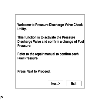
Activate the Pressure Discharge Valve Check
- HINT:
- This is the procedure for troubleshooting fuel pressure control malfunctions and combustion problems.
- Malfunctions can be determined by checking the fuel pressure when performing a fuel cut and operating the pressure discharge valve with the GTS.
- During "Pressure Discharge Valve Check", the GTS measures the fuel pressure while the engine is running, after the engine is stopped, and after the pressure discharge valve operates.
Connect the GTS to the DLC3.
Turn the engine switch on (IG).
Turn the GTS on.
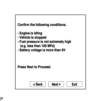
- NOTICE:
- Confirm the following conditions:
- Engine is idling.
- Vehicle is stopped.
- Fuel pressure is not extremely high (below 100000 kPa).
- Fuel pressure is not extremely low (higher than 26000 kPa).
- Fuel pressure sensor is normal.
- Battery voltage is higher than 8 V.
- HINT:
- When the common rail pressure is unstable, the fuel pressure may decrease to a level where the test cannot be performed. In this situation, wait until the common rail pressure meets the test condition, and then perform the test.
Enter the following menus: Engine and ECT / Utility / Pressure Discharge Valve Check.
Press "Next".
Press "Next" again to proceed.
Select the check type "Valve Check for Graph".
- Press "Next" again to proceed.
- Press "Start" again to proceed.
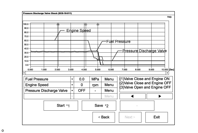
*1: When "Start" is pressed, the pressure discharge valve check begins.
*2: If "Save" is pressed after the pressure discharge valve check, the data recorded during the valve check can be saved.
- Press "Next" again to proceed.
Select the check type "Close to Open Check" or "Always Closed Check".
- HINT:
- "Close to Open Check" opens the pressure discharge valve after the engine stops.
- "Always Closed Check" holds the pressure discharge valve closed during the check.
- Press "Next".
- Perform troubleshooting based on the measurement results.
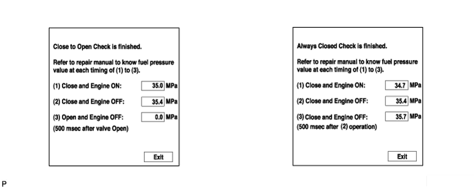
- HINT:
- During "Close to Open Check", if there is no large change in fuel pressure when the pressure discharge valve is closed while the engine is running and after the engine is stopped, and if the value is 0 kPa when the pressure discharge valve is open, the system is normal.
- Perform "Always Closed Check" if the value is not 0 kPa when the pressure discharge valve is open during "Close to Open Check". If the results are the same as during "Close to Open Check", there is a pressure discharge valve operation malfunction.
- If the fuel temperature is high, perform "Pressure Discharge Valve Check" after the fuel has cooled to the outside air temperature.
- If a large amount of fuel is leaking, the fuel pressure decreases when the engine is stopped. However, the condition of the pressure discharge valve can still be determined by comparing the measurement results of "Close to Open Check" and "Always Closed Check".