Theft Deterrent System (W/ Entry And Start System) Theft Warning Siren Circuit
DESCRIPTION
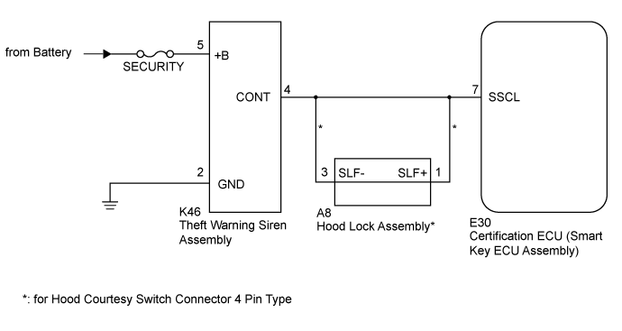
WIRING DIAGRAM
INSPECTION PROCEDURE
PERFORM ACTIVE TEST USING INTELLIGENT TESTER (THEFT WARNING SIREN)
CHECK HARNESS AND CONNECTOR (THEFT WARNING SIREN - BATTERY AND BODY GROUND)
CHECK HARNESS AND CONNECTOR (CERTIFICATION ECU [SMART KEY ECU ASSEMBLY] - THEFT WARNING SIREN)
CHECK THEFT WARNING SIREN (OPERATION)
CHECK HARNESS AND CONNECTOR (HOOD LOCK ASSEMBLY - CERTIFICATION ECU [SMART KEY ECU ASSEMBLY AND THEFT WARNING SIREN)
THEFT DETERRENT SYSTEM (w/ Entry and Start System) - Theft Warning Siren Circuit |
DESCRIPTION
The theft warning siren sounds if either of the following condition is met:- The theft deterrent system is in the alarm sounding state.
- The theft warning siren is in the armed state when +B, GND or the communication line is open.
WIRING DIAGRAM
INSPECTION PROCEDURE
- NOTICE:
- When replacing the theft warning siren assembly, refer to the Service Bulletin.
- Inspect the fuses for circuits related to this system before performing the following inspection procedure.
| 1.PERFORM ACTIVE TEST USING INTELLIGENT TESTER (THEFT WARNING SIREN) |
Operate the intelligent tester according to the steps on the display and select "Active Test".
Entry&StartTester Display
| Test Part
| Control Range
| Diagnostic Note
|
Security Horn2
| Theft warning siren
| ON / OFF
| -
|
- OK:
- Siren operates normally.
| OK |
|
|
|
| REPLACE CERTIFICATION ECU (SMART KEY ECU ASSEMBLY) |
|
| 2.CHECK HARNESS AND CONNECTOR (THEFT WARNING SIREN - BATTERY AND BODY GROUND) |
Disconnect the K46 theft warning siren assembly connector.
Measure the voltage according to the value(s) in the table below.
- Standard Voltage:
Tester Connection
| Condition
| Specified Condition
|
K46-5 (+B) - Body ground
| Always
| 11 to 14 V
|
Measure the resistance according to the value(s) in the table below.
- Standard Resistance:
Tester Connection
| Condition
| Specified Condition
|
K46-2 (GND) - Body ground
| Always
| Below 1 Ω
|
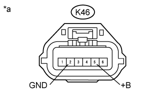
Text in Illustration*a
| Front view of wire harness connector
(to Theft Warning Siren Assembly)
|
| | REPAIR OR REPLACE HARNESS OR CONNECTOR |
|
|
| 3.CHECK HARNESS AND CONNECTOR (CERTIFICATION ECU [SMART KEY ECU ASSEMBLY] - THEFT WARNING SIREN) |
Disconnect the E30 certification ECU (smart key ECU assembly) connector.
Disconnect the K46 theft warning siren assembly connector.
Measure the resistance according to the value(s) in the table below.
- Standard Resistance:
Tester Connection
| Condition
| Specified Condition
|
E30-7 (SSCL) - K46-4 (CONT)
| Always
| Below 1 Ω
|
E30-7 (SSCL) - Body ground
| Always
| 10 kΩ or higher
|
ResultResult
| Proceed to
|
OK
| A
|
NG (except Hood Courtesy Switch Connector 4 Pin Type)
| B
|
NG (for Hood Courtesy Switch Connector 4 Pin Type)
| C
|
| | REPAIR OR REPLACE HARNESS OR CONNECTOR |
|
|
| |
|
| 4.CHECK THEFT WARNING SIREN (OPERATION) |
Temporarily replace the theft warning siren assembly with a new or known good one (refer to the Service Bulletin).
Check that the theft warning siren operates normally.
- OK:
- Operates normally.
| | REPLACE CERTIFICATION ECU (SMART KEY ECU ASSEMBLY) |
|
|
| OK |
|
|
|
| END (THEFT WARNING SIREN ASSEMBLY IS DEFECTIVE) |
|
| 5.CHECK HARNESS AND CONNECTOR (HOOD LOCK ASSEMBLY - CERTIFICATION ECU [SMART KEY ECU ASSEMBLY AND THEFT WARNING SIREN) |
Disconnect the E30 certification ECU (smart key ECU assembly) connector.
Disconnect the A8 hood lock assembly connector.
Disconnect the K46 theft warning siren assembly connector.
Measure the resistance according to the value(s) in the table below.
- Standard Resistance:
Tester Connection
| Condition
| Specified Condition
|
A8-1 (SLF+) - E30-7 (SSCL)
| Always
| Below 1 Ω
|
A8-3 (SLF-) - K46-4 (CONT)
| Always
| Below 1 Ω
|
A8-1 (SLF+) - Body ground
| Always
| 10 kΩ or higher
|
A8-3 (SLF-) - Body ground
| Always
| 10 kΩ or higher
|
| | REPAIR OR REPLACE HARNESS OR CONNECTOR |
|
|