Audio And Visual System (W/ Multi-Display) Radio Broadcast Cannot Be Received Or Poor Reception
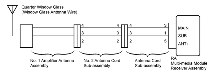
WIRING DIAGRAM
INSPECTION PROCEDURE
CHECK MULTI-MEDIA MODULE RECEIVER ASSEMBLY
CHECK OPTIONAL COMPONENTS
CHECK MULTI-MEDIA MODULE RECEIVER ASSEMBLY
CHECK QUARTER WINDOW ASSEMBLY (WINDOW GLASS ANTENNA WIRE)
INSPECT MULTI-MEDIA MODULE RECEIVER ASSEMBLY
CHECK ANTENNA CORD SUB-ASSEMBLY
CHECK NO. 2 ANTENNA CORD SUB-ASSEMBLY
CHECK NO. 1 AMPLIFIER ANTENNA ASSEMBLY
AUDIO AND VISUAL SYSTEM (w/ Multi-display) - Radio Broadcast cannot be Received or Poor Reception |
WIRING DIAGRAM
INSPECTION PROCEDURE
- NOTICE:
- Check that the antenna cable is properly installed and does not have any sharp bends, pinching or loose connections.
| 1.CHECK MULTI-MEDIA MODULE RECEIVER ASSEMBLY |
Check the radio automatic station search function.
Check the radio automatic station search function by activating it.
- OK:
- Automatic station search function stops on a station
| 2.CHECK OPTIONAL COMPONENTS |
Check if any optional components that may decrease reception capacity, such as sunshade film or a telephone antenna, are installed.
- NOTICE:
- Do not remove optional components without permission of the customer.
- OK:
- Optional components are installed.
| | REMOVE OPTIONAL COMPONENTS AND CHECK AGAIN (SEE NOTICE ABOVE) |
|
|
| 3.CHECK MULTI-MEDIA MODULE RECEIVER ASSEMBLY |
Remove the antenna connector from the multi-media module receiver assembly.
Turn the engine switch on (ACC) with the multi-media module receiver assembly connector connected.
Turn on the radio and turn into AM mode.
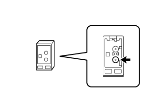
Place a screwdriver, thin wire or other metal object on the multi-media module receiver assembly antenna jack and check that noise can be heard from the speakers.
- OK:
- Noise can be heard from the speaker.
| | REPLACE MULTI-MEDIA MODULE RECEIVER ASSEMBLY (Click here) |
|
|
| 4.CHECK QUARTER WINDOW ASSEMBLY (WINDOW GLASS ANTENNA WIRE) |
Inspect the quarter window glass (window glass antenna wire) (Click here).
| 5.INSPECT MULTI-MEDIA MODULE RECEIVER ASSEMBLY |
Disconnect the multi-media module receiver assembly connector.
Measure the voltage according to the value(s) in the table below.
- Standard Voltage:
Tester Connection
| Switch Condition
| Specified Condition
|
RA-5 (ANT+) - Body ground
| Engine switch on (ACC), radio switch on and FM or AM selected
| 11 to 14 V
|
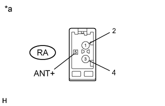
Text in Illustration*a
| Component without harness connected
(Multi-media Module Receiver Assembly)
|
| | REPLACE MULTI-MEDIA MODULE RECEIVER ASSEMBLY (Click here) |
|
|
| 6.CHECK ANTENNA CORD SUB-ASSEMBLY |
Remove the antenna connector from the multi-media module receiver assembly.
Remove the antenna connector from the No. 2 antenna cord sub-assembly.
Measure the resistance according to the value(s) in the table below.
- Standard Resistance:
Tester Connection
| Condition
| Specified Condition
|
RA-3 (MAIN) - 4
| Always
| Below 1 Ω
|
RA-1 (SUB) - 3
| Always
| Below 1 Ω
|
RA-5 (ANT+) - 2
| Always
| Below 1 Ω
|
RA-3 (MAIN) or 4 - Body ground
| Always
| 10 kΩ or higher
|
RA-1 (SUB) or 3 - Body ground
| Always
| 10 kΩ or higher
|
RA-5 (ANT+) or 2 - Body ground
| Always
| 10 kΩ or higher
|
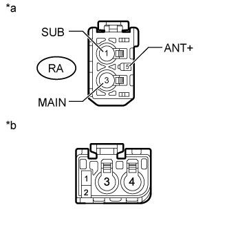
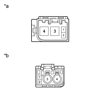
Text in Illustration*a
| Front view of wire harness connector
(to Multi-media Module Receiver Assembly)
|
*b
| Front view of wire harness connector
(to No. 2 Antenna Cord Sub-assembly)
|
| 7.CHECK NO. 2 ANTENNA CORD SUB-ASSEMBLY |
Remove the antenna connector from the antenna cord sub-assembly.
Remove the antenna connector from the No. 1 amplifier antenna assembly.
Measure the resistance according to the value(s) in the table below.
- Standard Resistance:
Tester Connection
| Condition
| Specified Condition
|
4 - 4
| Always
| Below 1 Ω
|
3 - 3
| Always
| Below 1 Ω
|
2 - 2
| Always
| Below 1 Ω
|
4 or 4 - Body ground
| Always
| 10 kΩ or higher
|
3 or 3 - Body ground
| Always
| 10 kΩ or higher
|
2 or 2 - Body ground
| Always
| 10 kΩ or higher
|
Text in Illustration*a
| Front view of wire harness connector
(to Antenna Cord Sub-assembly)
|
*b
| Front view of wire harness connector
(to No. 1 Amplifier Antenna Assembly)
|
| | REPLACE NO. 2 ANTENNA CORD SUB-ASSEMBLY (Click here) |
|
|
| 8.CHECK NO. 1 AMPLIFIER ANTENNA ASSEMBLY |
Replace the No. 1 amplifier antenna assembly new or known good one and check if radio broadcasts can be received normally (Click here).
- OK:
- Radio broadcasts can be received.
| | REPLACE MULTI-MEDIA MODULE RECEIVER ASSEMBLY (Click here) |
|
|
| OK |
|
|
|
| END (NO. 1 AMPLIFIER ANTENNA ASSEMBLY IS DEFECTIVE) |
|