Audio And Visual System (W/ Multi-Display) Stereo Component Amplifier Power Source Circuit
DESCRIPTION
WIRING DIAGRAM
INSPECTION PROCEDURE
CHECK HARNESS AND CONNECTOR (STEREO COMPONENT AMPLIFIER ASSEMBLY - BATTERY AND BODY GROUND)
AUDIO AND VISUAL SYSTEM (w/ Multi-display) - Stereo Component Amplifier Power Source Circuit |
DESCRIPTION
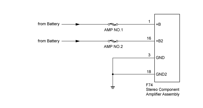
This circuit provides power to the stereo component amplifier assembly.
WIRING DIAGRAM
INSPECTION PROCEDURE
- NOTICE:
- Inspect the fuses for circuits related to this system before performing the following inspection procedure.
| 1.CHECK HARNESS AND CONNECTOR (STEREO COMPONENT AMPLIFIER ASSEMBLY - BATTERY AND BODY GROUND) |
Disconnect the stereo component amplifier assembly connectors.
Measure the resistance according to the value(s) in the table below.
- Standard Resistance:
Tester Connection
| Condition
| Specified Condition
|
F74-3 (GND) - Body ground
| Always
| Below 1 Ω
|
F74-18 (GND2) - Body ground
| Always
| Below 1 Ω
|
Measure the voltage according to the value(s) in the table below.
- Standard Voltage:
Tester Connection
| Condition
| Specified Condition
|
F74-1 (+B) - Body ground
| Always
| 11 to 14 V
|
F74-16 (+B2) - Body ground
| Always
| 11 to 14 V
|
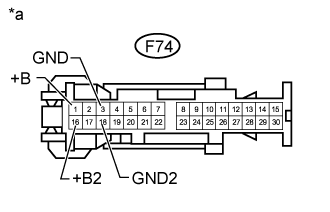
Text in Illustration*a
| Front view of wire harness connector
(to Stereo Component Amplifier Assembly)
|
| | REPAIR OR REPLACE HARNESS OR CONNECTOR |
|
|
| OK |
|
|
|
| PROCEED TO NEXT SUSPECTED AREA SHOWN IN PROBLEM SYMPTOMS TABLE (Click here) |
|