Navigation System Illumination Circuit
DESCRIPTION
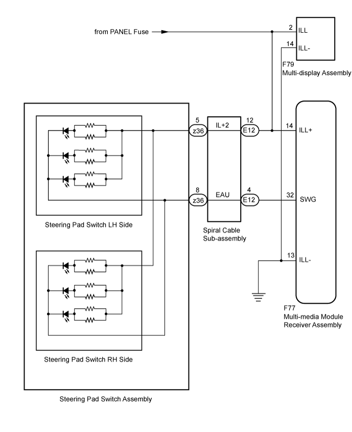
WIRING DIAGRAM
INSPECTION PROCEDURE
CHECK ILLUMINATION
CHECK HARNESS AND CONNECTOR (ILLUMINATION SIGNAL)
INSPECT STEERING PAD SWITCH ASSEMBLY
INSPECT SPIRAL CABLE SUB-ASSEMBLY
CHECK HARNESS AND CONNECTOR (MULTI-MEDIA MODULE RECEIVER ASSEMBLY, MULTI-DISPLAY ASSEMBLY - SPIRAL CABLE SUB-ASSEMBLY)
CHECK HARNESS AND CONNECTOR (MULTI-DISPLAY ASSEMBLY - BATTERY AND BODY GROUND)
CHECK HARNESS AND CONNECTOR (MULTI-MEDIA MODULE RECEIVER ASSEMBLY - BATTERY AND BODY GROUND)
NAVIGATION SYSTEM - Illumination Circuit |
DESCRIPTION
Power is supplied to the multi-media module receiver assembly, multi-display assembly and steering pad switch assembly illumination when the light control switch is in the tail or head position.
WIRING DIAGRAM
INSPECTION PROCEDURE
- NOTICE:
- The vehicle is equipped with a Supplemental Restraint System (SRS) which includes components such as airbags. Before servicing (including removal or installation of parts), be sure to read the precaution for Supplemental Restraint System (Click here).
- Inspect the fuse for circuits related to this system before performing the following inspection procedure.
Check if the illumination for the multi-media module receiver assembly, multi-display assembly, steering pad switch assembly or others (hazard switch etc.) comes on when the light control switch is turned to the head or tail position.
ResultResult
| Proceed to
|
Illumination comes on for all components except steering pad switch assembly.
| A
|
Illumination comes on for all components except multi-display assembly.
| B
|
Illumination comes on for all components except multi-media module receiver assembly.
| C
|
No illumination comes on (multi-media module receiver assembly, steering pad switch, hazard switch, heater control switch, etc.).
| D
|
| 2.CHECK HARNESS AND CONNECTOR (ILLUMINATION SIGNAL) |
Disconnect the spiral cable sub-assembly connector.
Measure the voltage according to the value(s) in the table below.
- Standard Voltage:
Tester Connection
| Switch Condition
| Specified Condition
|
E12-12 (IL+2) - Body ground
| Light control switch in the tail or head position
| 11 to 14 V
|
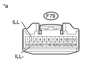
Text in Illustration*a
| Front view of wire harness connector
(to Spiral Cable Sub-assembly)
|
| | REPAIR OR REPLACE HARNESS OR CONNECTOR |
|
|
| 3.INSPECT STEERING PAD SWITCH ASSEMBLY |
Remove the steering pad switch assembly (Click here).
Inspect the steering pad switch assembly (Click here).
| 4.INSPECT SPIRAL CABLE SUB-ASSEMBLY |
Remove the spiral cable sub-assembly (Click here).
Inspect the spiral cable sub-assembly (Click here).
| 5.CHECK HARNESS AND CONNECTOR (MULTI-MEDIA MODULE RECEIVER ASSEMBLY, MULTI-DISPLAY ASSEMBLY - SPIRAL CABLE SUB-ASSEMBLY) |
Disconnect the F77 multi-media module receiver assembly connector.
Disconnect the F79 multi-display assembly connector.
Disconnect the E12 spiral cable sub-assembly connector.
Measure the resistance according to the value(s) in the table below.
- Standard Resistance:
Tester Connection
| Condition
| Specified Condition
|
F77-14 (ILL+) - E12-12 (IL+2)
| Always
| Below 1 Ω
|
F77-32 (SWG) - E12-4 (EAU)
| Always
| Below 1 Ω
|
F79-2 (ILL) - E12-12 (IL+2)
| Always
| Below 1 Ω
|
F77-14 (ILL+) - Body ground
| Always
| 10 kΩ or higher
|
F77-32 (SWG) - Body ground
| Always
| 10 kΩ or higher
|
F79-2 (ILL) - Body ground
| Always
| 10 kΩ or higher
|
| | REPAIR OR REPLACE HARNESS OR CONNECTOR |
|
|
| OK |
|
|
|
| PROCEED TO NEXT SUSPECTED AREA SHOWN IN PROBLEM SYMPTOMS TABLE (Click here) |
|
| 6.CHECK HARNESS AND CONNECTOR (MULTI-DISPLAY ASSEMBLY - BATTERY AND BODY GROUND) |
Disconnect the multi-display assembly connector.
Measure the resistance according to the value(s) in the table below.
- Standard Resistance:
Tester Connection
| Condition
| Specified Condition
|
F79-14 (ILL-) - Body ground
| Always
| Below 1 Ω
|
Measure the voltage according to the value(s) in the table below.
- Standard Voltage:
Tester Connection
| Switch Condition
| Specified Condition
|
F79-2 (ILL) - Body ground
| Light control switch in the tail or head position
| 11 to 14 V
|
Text in Illustration*a
| Front view of wire harness connector
(to Multi-display Assembly)
|
| | REPAIR OR REPLACE HARNESS OR CONNECTOR |
|
|
| 7.CHECK HARNESS AND CONNECTOR (MULTI-MEDIA MODULE RECEIVER ASSEMBLY - BATTERY AND BODY GROUND) |
Disconnect the multi-media module receiver assembly connector.
Measure the voltage according to the value(s) in the table below.
- Standard Voltage:
Tester Connection
| Switch Condition
| Specified Condition
|
F77-14 (ILL+) - Body ground
| Light control switch in the tail or head position
| 11 to 14 V
|
Measure the resistance according to the value(s) in the table below.
- Standard Resistance:
Tester Connection
| Condition
| Specified Condition
|
F77-13 (ILL-) - Body ground
| Always
| Below 1 Ω
|
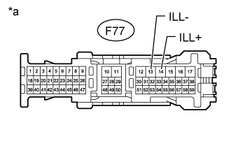
Text in Illustration*a
| Front view of wire harness connector
(to Multi-media Module Receiver Assembly)
|
| | REPAIR OR REPLACE HARNESS OR CONNECTOR |
|
|
| OK |
|
|
|
| REPLACE MULTI-MEDIA MODULE RECEIVER ASSEMBLY (Click here) |
|