Parking Brake Cable Installation
Brake. Land Cruiser. Urj200, 202 Grj200 Vdj200
INSTALL NO. 2 PARKING BRAKE CABLE ASSEMBLY
INSTALL NO. 3 PARKING BRAKE CABLE ASSEMBLY
CONNECT NO. 3 PARKING BRAKE CABLE ASSEMBLY
INSTALL PARKING BRAKE SHOE LEVER LH
INSTALL NO. 2 PARKING BRAKE SHOE ASSEMBLY LH
INSTALL NO. 1 PARKING BRAKE SHOE ASSEMBLY LH
INSTALL PARKING BRAKE SHOE RETURN SPRING
CHECK PARKING BRAKE INSTALLATION
INSTALL REAR DISC
CONNECT REAR DISC BRAKE CYLINDER ASSEMBLY LH
INSTALL REAR NO. 2 SUSPENSION CONTROL ACCUMULATOR BRACKET
INSTALL HEIGHT CONTROL UNIT PROTECTOR PIPE
ADJUST PARKING BRAKE
INSTALL REAR WHEEL
INSTALL LOWER CONSOLE BOX (w/o Console Box Lid)
INSTALL COOLING BOX ASSEMBLY (w/ Cool Box)
INSTALL REAR CONSOLE BOX SUB-ASSEMBLY (w/o Cool Box)
Parking Brake Cable -- Installation |
- HINT:
- Use the same procedures for the LH side and RH side.
- The procedures listed below are for the LH side.
| 1. INSTALL NO. 2 PARKING BRAKE CABLE ASSEMBLY |
Install the No. 2 parking brake cable clamp.
Install the No. 2 parking brake cable with the 6 bolts.
- Torque:
- 13 N*m{127 kgf*cm, 9 ft.*lbf}
Install the fuel tank (Click here).
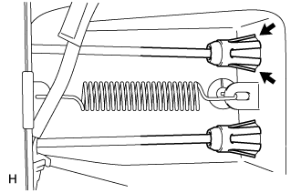
Attach the claws of the No. 2 parking brake cable.
Connect the No. 2 parking brake cable to the No. 1 parking brake pull rod.
| 2. INSTALL NO. 3 PARKING BRAKE CABLE ASSEMBLY |
Install the No. 3 parking brake cable clamp.
Install the No. 3 parking brake cable with the 6 bolts.
- Torque:
- 13 N*m{127 kgf*cm, 9 ft.*lbf}
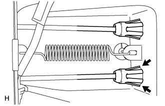
Attach the claws of the No. 3 parking brake cable.
Connect the No. 3 parking brake cable to the No. 1 parking brake pull rod.
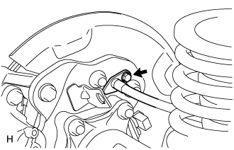
| 3. CONNECT NO. 3 PARKING BRAKE CABLE ASSEMBLY |
Connect the No. 3 parking brake cable with the bolt.
- Torque:
- 8.0 N*m{82 kgf*cm, 71 in.*lbf}
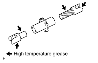
| 4. INSTALL PARKING BRAKE SHOE LEVER LH |
Apply high temperature grease to the parking brake anchor block.
Install the parking brake shoe lever to the No. 3 parking brake cable.
- NOTICE:
- Be carefully to distinguish between the parking brake shoe lever RH and LH.
| 5. INSTALL NO. 2 PARKING BRAKE SHOE ASSEMBLY LH |
Apply high temperature grease to the areas of the backing plate that contact the shoe.
Using SST, install the No. 2 parking brake shoe with the shoe hold down spring pin, compression spring and shoe hold down spring cup.
- SST
- 09718-00011
| 6. INSTALL NO. 1 PARKING BRAKE SHOE ASSEMBLY LH |
Apply high temperature grease to the areas of the backing plate that contact the shoe.
Apply high temperature grease to the thread and all joining areas of the parking brake shoe adjuster screw set.
Set the No. 1 parking brake shoe and shoe adjuster screw set in place.
Connect the tension spring.
Using SST, install the shoe hold down spring pin, compression spring and shoe hold down spring cup.
- SST
- 09718-00011
| 7. INSTALL PARKING BRAKE SHOE RETURN SPRING |
Using SST, install the shoe return spring.
- SST
- 09703-30011
| 8. CHECK PARKING BRAKE INSTALLATION |
Check that each part is installed properly.
Align the matchmarks, and then install the rear disc.
- HINT:
- When replacing the rear disc with a new one, select the installation position where the rear disc has the minimum runout.
| 10. CONNECT REAR DISC BRAKE CYLINDER ASSEMBLY LH |
Connect the rear disc brake cylinder with 2 new bolts.
- Torque:
- 95 N*m{969 kgf*cm, 70 ft.*lbf}
- NOTICE:
- Do not twist the brake hose.
- Make sure that the bolts are free from damage and foreign matter.
- Do not overtighten the bolts.
| 11. INSTALL REAR NO. 2 SUSPENSION CONTROL ACCUMULATOR BRACKET |
Install the bracket to the shock absorber control valve with the bolt.
- Torque:
- 18 N*m{184 kgf*cm, 13 ft.*lbf}
| 12. INSTALL HEIGHT CONTROL UNIT PROTECTOR PIPE |
Install the protector pipe with the 6 bolts.
- Torque:
- 16 N*m{163 kgf*cm, 12 ft.*lbf}
(Click here)
- Torque:
- for Aluminum Wheel:
- 131 N*m{1336 kgf*cm, 97 ft.*lbf}
- for Steel Wheel:
- 209 N*m{2131 kgf*cm, 154 ft.*lbf}
| 15. INSTALL LOWER CONSOLE BOX (w/o Console Box Lid) |
(Click here)
| 16. INSTALL COOLING BOX ASSEMBLY (w/ Cool Box) |
(Click here)
| 17. INSTALL REAR CONSOLE BOX SUB-ASSEMBLY (w/o Cool Box) |
(Click here)