Park / Neutral Position Switch -- Installation |
| 1. INSTALL PARK/NEUTRAL POSITION SWITCH ASSEMBLY |
- HINT:
- Make sure that the manual valve lever shaft has not been rotated prior to installing the park/neutral position switch as the detent spring may become detached from the manual valve lever shaft.
Clean the bolt and the bolt hole.
Apply adhesive to 2 or 3 threads on the end of the bolt.
- Adhesive:
- Toyota Genuine Adhesive 1344, Three Bond 1344 or equivalent
Install the switch to the manual valve shaft.
Temporarily install the park/neutral position switch assembly with the bolt.
- HINT:
- Tighten the bolt to the specified torque when adjusting the park/neutral position switch assembly.
 |
Install the lock washer and the nut.
- Torque:
- 6.9 N*m{70 kgf*cm, 61 in.*lbf}
 |
Temporarily install the control shaft lever RH.
 |
Turn the control shaft lever RH counterclockwise until it stops, and then turn it clockwise 2 notches to set it to the N position.
 |
Remove the control shaft lever RH.
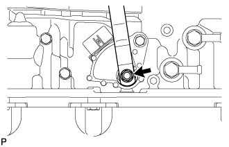
Align the groove with the neutral basic line.
 |
Hold the switch in the position described above and tighten the bolt.
- Torque:
- 13 N*m{133 kgf*cm, 10 ft.*lbf}
Using a screwdriver, bend the tabs of the lock washer.
 |
Install the transmission control rod bush and collar to the transmission control shaft lever RH.
Install the transmission control shaft lever RH with the spring washer and nut.
- Torque:
- 16 N*m{163 kgf*cm, 12 ft.*lbf}
|
Connect the switch connector.
| 2. CONNECT FLOOR SHIFT GEAR SHIFTING ROD SUB-ASSEMBLY |
 |
Connect the shifting rod to the transmission control shaft lever RH with the pin.
Install a new clip.
| 3. INSPECT SHIFT LEVER POSITION |
When moving the shift lever from P to R with the ignition switch ON and the brake pedal depressed, make sure that it moves smoothly and correctly into position.
Check that the shift lever does not stop when moving the shift lever from R to P, and check that the shift lever does not stick when moving the shift lever from D to S.
Start the engine and make sure that the vehicle moves forward after moving the shift lever from N to D and moves rearward after moving the shift lever to R.
If the operation cannot be performed as specified, inspect the park/neutral position switch assembly and check the shift lever assembly installation condition.
| 4. INSPECT PARK/NEUTRAL POSITION SWITCH ASSEMBLY |
| 5. INSTALL FRONT EXHAUST PIPE ASSEMBLY (w/ DPF) |
Install a new gasket and the front exhaust pipe to the monolithic converter RH with 3 new nuts.
- Torque:
- 48 N*m{489 kgf*cm, 35 ft.*lbf}
Check the free length.
Using a vernier caliper, measure the free length of the compression spring.
- Free length:
- 43 mm (1.69 in.)
 |
Install a new gasket and connect the front exhaust pipe assembly with the 2 bolts and 2 compression springs.
- Torque:
- 43 N*m{438 kgf*cm, 32 ft.*lbf}
Attach the clamp and connect the exhaust gas temperature sensor connector.
Text in Illustration *1 Tape *2 Stopper *3 Clip *4 Paint Mark *a 2 to 7 mm (0.0787 to 0.276 in.) - HINT:
- Make sure that the tape is in the position shown in the illustration.
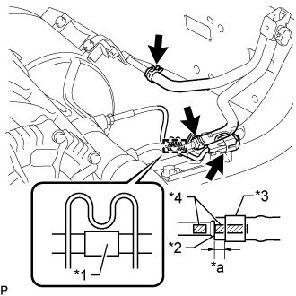 |
Install 2 new clips to the 2 air hoses.
Connect the 2 air hoses to the front exhaust pipe.
- NOTICE:
- Align the paint marks of the front exhaust pipe and air hose and push on the air hose until it contacts the stopper.
- Make sure the clip is 4 to 10 mm (0.157 to 0.394 in.) from the end of the air hose when installing the clip.
- Make sure that there is no slack in the air hose, and that it is not twisted or bent.
- Take care not to damage the inner or outer surface of the air hose when installing it. If the air hose is damaged, replace it with a new one.
Connect the air fuel ratio sensor connector.
| 6. INSPECT FOR EXHAUST GAS LEAK |