Dtc B2278 Engine Switch Circuit Malfunction
DESCRIPTION
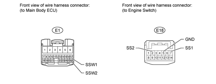
WIRING DIAGRAM
INSPECTION PROCEDURE
READ VALUE USING INTELLIGENT TESTER (START SWITCH 1, 2)
CHECK WHETHER DTC OUTPUT RECURS
INSPECT ENGINE SWITCH
CHECK HARNESS AND CONNECTOR (MAIN BODY ECU - ENGINE SWITCH AND BODY GROUND)
DTC B2278 Engine Switch Circuit Malfunction |
DESCRIPTION
This DTC is stored when: 1) a malfunction is detected between the main body ECU and the engine switch; or 2) either of the switches inside the engine switch is malfunctioning.DTC Code
| Detection Condition
| Trouble Area
|
B2278
| Communication is abnormal between the main body ECU and engine switch or the engine switch is defective.
| - Main body ECU
- Engine switch
- Harness or connector
|
WIRING DIAGRAM
INSPECTION PROCEDURE
| 1.READ VALUE USING INTELLIGENT TESTER (START SWITCH 1, 2) |
Use the Data List to check if the engine switch is functioning properly.
Main BodyTester Display
| Measurement Item/Range
| Normal Condition
| Diagnostic Note
|
Start Switch 1
| Start Switch 1/ON or OFF
| ON: Engine switch on (IG)
OFF: Engine switch off
| -
|
Start Switch 2
| Start Switch 2/ON or OFF
| ON: Engine switch on (IG)
OFF: Engine switch off
| -
|
- OK:
- When the engine switch is turned on (IG), ON is displayed on the intelligent tester.
| 2.CHECK WHETHER DTC OUTPUT RECURS |
Clear the DTCs (Click here).
Turn the engine switch on (IG), and check whether DTC B2278 is output.
ResultResult
| Proceed to
|
No DTC output
| A
|
DTC B2278 output
| B
|
Disconnect the E18 engine switch connector.
Measure the resistance according to the value(s) in the table below.
- Standard Resistance:
Tester Connection
| Switch Condition
| Specified Condition
|
7 (SS1) - 5 (GND)
| Pushed
| Below 1 Ω
|
2 (SS2) - 5 (GND)
| Pushed
| Below 1 Ω
|
7 (SS1) - 5 (GND)
| Not pushed
| 10 kΩ or higher
|
2 (SS2) - 5 (GND)
| Not pushed
| 10 kΩ or higher
|
ResultResult
| Proceed to
|
Within specified range
| A
|
Outside specified range (for 1GR-FE)
| B
|
Outside specified range (for 1UR-FE)
| C
|
Outside specified range (for 3UR-FE)
| D
|
Outside specified range (for 1VD-FTV)
| E
|
| 4.CHECK HARNESS AND CONNECTOR (MAIN BODY ECU - ENGINE SWITCH AND BODY GROUND) |
Disconnect the E1 main body ECU connector.
Disconnect the E18 engine switch connector.
Measure the resistance according to the value(s) in the table below.
- Standard Resistance:
Tester Connection
| Condition
| Specified Condition
|
E1-17 (SSW1) - E18-7 (SS1)
| Always
| Below 1 Ω
|
E1-16 (SSW2) - E18-2 (SS2)
| Always
| Below 1 Ω
|
E18-5 (GND) - Body ground
| Always
| Below 1 Ω
|
E1-17 (SSW1) or E18-7 (SS1) - Body ground
| Always
| 10 kΩ or higher
|
E1-16 (SSW2) or E18-2 (SS2) - Body ground
| Always
| 10 kΩ or higher
|
| | REPAIR OR REPLACE HARNESS OR CONNECTOR |
|
|