Variable Gear Ratio Steering System -- Calibration |
- NOTICE:
- If parts between the steering wheel and tires have been removed/installed, replaced or adjusted, perform actuator angle neutral point calibration and initialization for the VGRS system, otherwise the steering wheel may become off-center.
- The VGRS ECU (steering control ECU) has been replaced or removed/installed.
- The steering actuator assembly has been replaced or removed/installed.
- The steering wheel assembly has been replaced or removed/installed.
- The steering column assembly has been replaced or removed/installed.
- The intermediate shaft assembly has been separated.
- The front wheel alignment has been adjusted.
- The power steering link assembly has been replaced or removed/installed.
- The steering wheel is still off-center after completing the steering sensor initialization.
| PERFORM ACTUATOR ANGLE NEUTRAL POINT CALIBRATION AND INITIALIZATION (When Using GTS) |
Position the tires straight ahead.
- NOTICE:
- Drive the vehicle to confirm that the steering wheel is centered.
Turn the engine switch off.
Connect the GTS to the DLC3.
Turn the engine switch on (IG).
Enter the following menus: Chassis / VGRS / Utility / Steering Angle Adjust.
According to the display on the GTS, perform actuator angle neutral point calibration and initialization.
| PERFORM ACTUATOR ANGLE NEUTRAL POINT CALIBRATION AND INITIALIZATION (When Using SST Check Wire) |
Position the tires straight ahead.
- NOTICE:
- Drive the vehicle to confirm that the steering wheel is centered.
Check for DTCs (Click here).
- HINT:
- If DTC C1591/51 is not stored, proceed to *A, and if it is stored, proceed to *B.
Perform actuator angle initialization.[*A]
- SST
- 09843-18040
- CAUTION:
- If the procedures from *1 to *2 are not completed within 1 minute, or if errors are made during these procedures, perform initialization again from the beginning.
Turn the engine switch off.
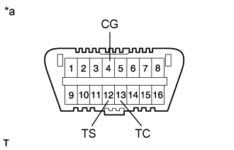
Using SST, connect terminals 12 (TS) and 4 (CG) of the DLC3.*1
Text in Illustration *a Front view of DLC3 Start the engine.
Center the steering wheel.
Using SST, connect terminals 13 (TC) and 4 (CG) of the DLC3.
Disconnect SST from terminal 12 (TS) of the DLC3 and turn the steering wheel to the left 180° or more.
Connect SST to terminal 12 (TS) of the DLC3.
Disconnect SST from terminal 13 (TC) of the DLC3 and turn the steering wheel to the right 180° or more.
Connect SST to terminal 13 (TC) of the DLC3.*2
- HINT:
- If "Check VGRS System" is displayed on the multi-information display, DTC 1591/51 is stored.
Confirm that the steering wheel is centered when facing the tires straight ahead.[*B]
- NOTICE:
- Drive the vehicle to confirm that the steering wheel is centered.
- HINT:
- If the steering wheel is off-center, proceed to *C, and if it is centered, proceed to *D.
Disable the system lock. [*C]
- NOTICE:
- Make sure the engine is not running.
Turn the engine switch off.
Disconnect the cable from the negative (-) battery terminal.
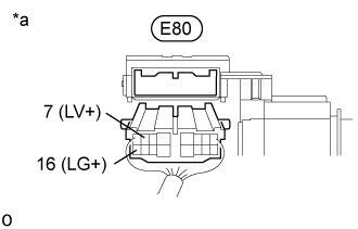
Disconnect the E80 steering actuator assembly connector.
Connect a jumper wire from terminal 7 (LV+) of the steering actuator assembly to the positive (+) 12 V battery terminal and a jumper wire from terminal 16 (LG+) of the steering actuator assembly to the negative (-) 12 V battery terminal.
Text in Illustration *a Rear view of wire harness connector
(to Steering Actuator Assembly)- NOTICE:
- Do not apply voltage for more than 3 minutes.
Center the steering wheel.
- HINT:
- If the centering of the spiral cable sub-assembly was not confirmed when the steering wheel was installed, confirm the centering of the spiral cable (Click here).
Perform system lock.
Disconnect the positive (+) and negative (-) 12 V battery jumper wires from the steering actuator assembly.
Connect the connector to the E80 steering actuator assembly.
Connect the cable to the negative (-) battery terminal.
Turn the steering wheel approximately 3° to the left and right. Confirm that the reaction force can be felt.
- NOTICE:
- Perform these procedures with the engine switch off.
Perform actuator angle neutral point calibration.[*D]
- SST
- 09843-18040
- HINT:
- Entering and exiting test mode completes the actuator angle adjustment.
Enter test mode (Click here).
Confirm that "VGRS Test Mode" is displayed on the multi-information display when test mode is activated.
- HINT:
- When test mode is activated, "VGRS Test Mode" will be displayed on the multi-information display, which indicates that the system has entered test mode.
- Wait approximately 5 seconds.
Exit test mode (Click here).